www.weg.net
11866576 Installation, Operation and Maintenance Manual – Synchronous Motors – S Line – Brushless – Horizontal l 33
5.3 EXCITATION CIRCUITS
The type of excitation circuit used in the asynchronous
starting of the brushless motor depends on the
application, and it is described in its specific
documentation.
5.3.1 Excitation circuit with voltage control
(Random)
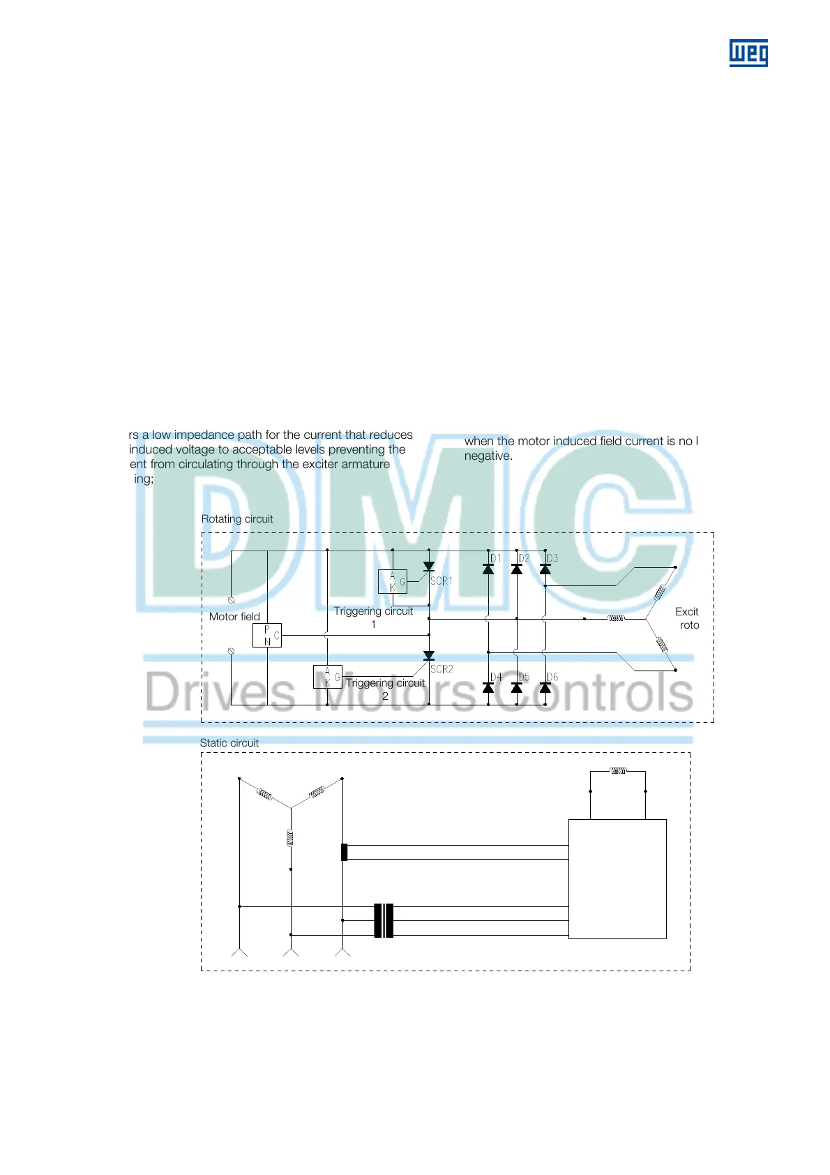
The circuit shown in Figure 5.1 works as follows:
During normal motor operation, the exciter rotor and the
D1-D6 diodes generate rectified DC voltage to supply
field current to the motor according to the exciter field
current supplied by an external controlled source.
During normal operation, the SCR1 and SCR2 thyristors
are not conducting;
During the motor starting, the rotating field generated by
the motor stator induces a very high alternate voltage in
the motor field winding which is proportional to the ratio
between the number of turns of the stator and the slip;
In order to prevent damages to the insulation system
and to the other rotor components, the exciter rectifier
offers a low impedance path for the current that reduces
the induced voltage to acceptable levels preventing the
current from circulating through the exciter armature
winding;
When the field induced current is in the positive
direction, the diode bridge will deviate the induced field
current with a small voltage drop;
When the induced field current is in the negative
direction, the alternate voltage of the field winding is
positive by means of the SCR1, SCR2 thyristors and in
the triggering circuits;
The circuit is arranged so that the triggering circuits
identify the full voltage. As the alternate voltage
increases, the triggering circuits make the SCRs
conduct;
The voltage level of the triggering circuits is specified to
be sufficiently above the normal operation field voltage;
When the motor gets close to the synchronous speed,
the induced field voltage and the frequency of this
voltage get close to zero;
The exciter field voltage, which until this moment
remained not applied by the external voltage supply and
control, can now be applied, increasing the exciter DC
voltage to the operation levels;
If the SCR1 and SCR2 thyristors are conducting when
the exciter has a significant voltage, the connection
between the crossing of SCR1 and SCR2 and the
exciter AC phase will allow the cut-off of the thyristors
when the motor induced field current is no longer
negative.
Figure 5.1: Triggering circuit with voltage control
Motor field
Exciter
stator
Exciter
rotor
Power supply
and control of
the exciter
field
Motor stator
CT
P
Triggering circuit
2
AC three-phase power supply
Static circuit
Rotating circuit
Triggering circuit
1
 Loading...


