www.weg.net
11866576 Installation, Operation and Maintenance Manual – Synchronous Motors – S Line – Brushless – Horizontal l 35
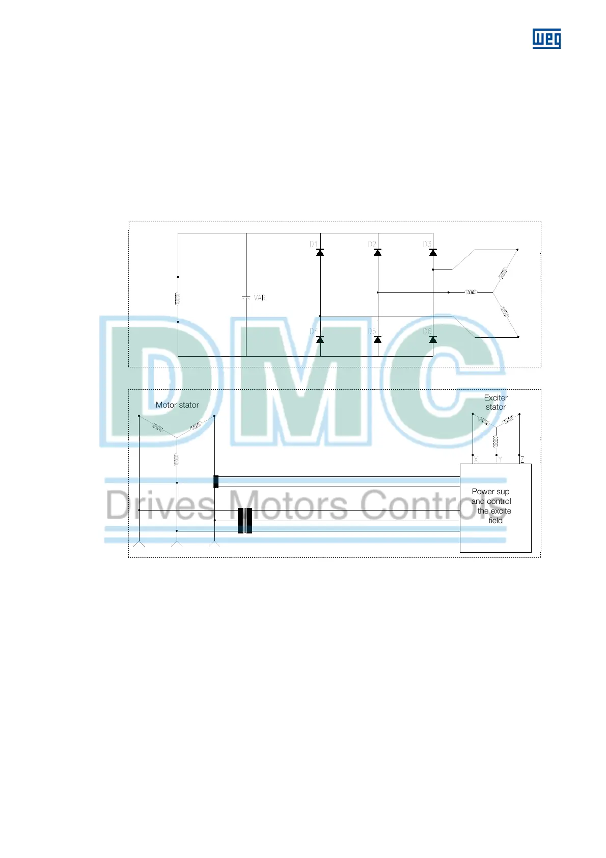
5.3.4 Excitation circuit for AC exciter
The circuit shown in Figure 5.3 used in brushless
synchronous motors with AC exciter for frequency
inverter drive system works as follows:
During normal operation, the exciter rotor and the D1-D6
diodes, which are fixed to the motor shaft, generate a
rectified DC voltage to supply field current to the motor
according to the exciter field current supplied separately
by an exciter drive in alternate current.
During the motor operation, the rotating field of the
exciter stator induces an alternate voltage on the exciter
rotor, even when the motor is completely stopped. The
field excitation is controlled by the exciter drive by
means of voltage amplitude;
The AC exciter phase sequence makes the slip increase
from 1 to normally 3 at maximum speed. That is why the
rotating field applied to the exciter stator must rotate in
the opposite direction of the motor rotation direction;
If the rotating field has the same direction of motor
rotation and they have the same speed, then the
induced voltage and current in the exciter rotor will be
zero;
This kind of rectifier configuration is not used for direct
start. Start this motor only by using a frequency inverter.
Figure 5.3: Triggering circuit for AC exciter.
Motor field
Exciter
rotor
Exciter
stator
Power supply
and control of
the exciter
field
Motor stator
AC three-phase power supply
 Loading...


