www.weg.net
11866576 Installation, Operation and Maintenance Manual – Synchronous Motors – S Line – Brushless – Horizontal l 47
7.10.3.6
Sleeve bearing operation
The system start, as well as the first hours of
operation, must be monitored carefully.
Before starting, check:
If the oil inlet and outlet tubes (if any) are clean. Clean
the tubes by pickling, if necessary;
If the used oil complies with the specification on the
nameplate;
The lubricant characteristics;
The oil level;
The alarm and trip temperatures set for the bearing.
During the first start, it is necessary to stay alert for
unusual vibrations or noises. If the bearing is not running
silently and smoothly, the motor must be shut down
immediately.
The motor must operate for several hours until the bearing
temperatures stabilize. In case of overheating of the
bearings, the motor must be shut down for inspection of
the bearings and temperature sensors.
Check if there is no oil leak through the plugs, gaskets or
shaft end.
7.10.3.7
Sleeve bearing maintenance
The sleeve bearing maintenance includes:
Periodic checking of the oil level and its lubricating
conditions;
Checking the bearing noise and vibration levels;
Monitoring of the operating temperatures and
retightening of the fastening and assembly screws;
In order to facilitate the heat exchange with the
environment, the frame must be kept clean, without
external oil or dust accumulation;
The NDE bearing is electrically insulated. The spherical
seat surfaces of the bearing shell on the frame are
covered with insulating material. Never remove this
cover;
The anti-rotation pin is also insulated, and the seals are
made of non-conducting material;
Temperature control devices that are in contact with the
bearing shell must also be properly insulated.
7.10.4
Protection setting
TTENTION
The following temperatures must be set on the
bearing protection system:
LARM: 110 ºC
TRIP: 120 ºC
The alarm temperature must be set for 10 ºC
above the operating temperature, not exceeding
the limit of 110 ºC.
7.10.5
Disassembly/assembly of the bearing
temperature sensors
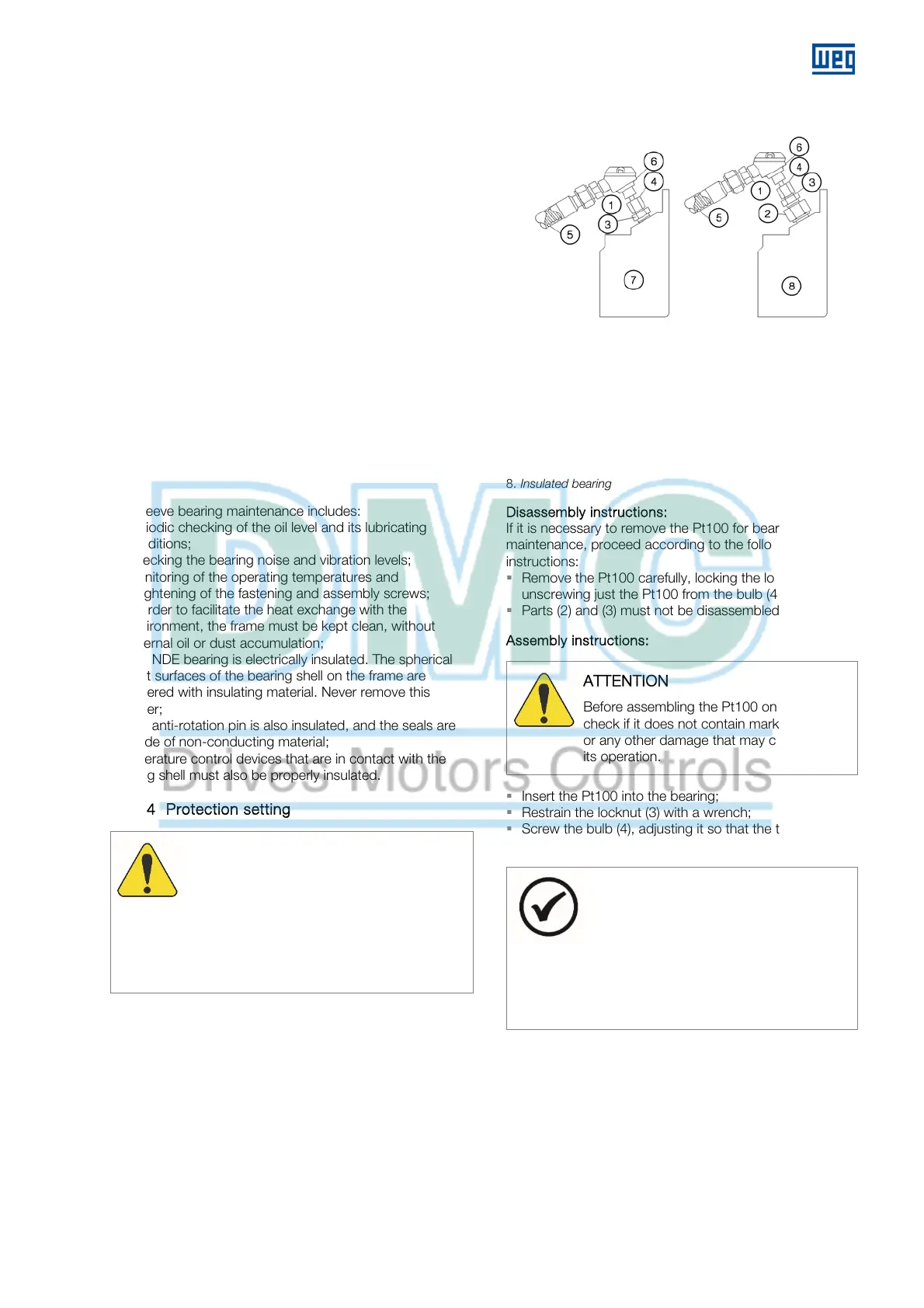
Figure 7.6: Pt100 on the bearings
Figure 7.6 legend:
1. Reduction nipple
2. Insulating adapter
3. Locknut
4. Bulb
5. Flexible metal tube
6. Pt-100 temperature sensor
7. Non-insulated bearing
8. Insulated bearing
Disassembly instructions:
If it is necessary to remove the Pt100 for bearing
maintenance, proceed according to the following
instructions:
Remove the Pt100 carefully, locking the locknut (3) and
unscrewing just the Pt100 from the bulb (4);
Parts (2) and (3) must not be disassembled.
Assembly instructions:
TTENTION
Before assembling the Pt100 on the bearing,
check if it does not contain marks of knock
or any other damage that may compromise
its operation.
Insert the Pt100 into the bearing;
Restrain the locknut (3) with a wrench;
Screw the bulb (4), adjusting it so that the tip of the
Pt100 touches the contact surface of the bearing.
NOTES
The assembly of the Pt100 on non-
insulated bearings must be done directly
on the bearing, without the insulating
adapter (2);
The tightening torque to assemble the
Pt100 and the adapters must not exceed
10 Nm.
 Loading...


