CHAPTER 3 - INSTALLATION AND CONNECTION
22
English
3.2.7 Control
and Signal
Connections
3.3 RECOMMENDED
SET-UPS
EMI - Electronic Interference
The Soft-Starter SSW-07 is developed to be used in industrial
systems (Class A) according to Standard EN60947-4-2.
It’s necessary to have a distance of 0.25 m (10 in) between the
Soft- Starter SSW-07 control cables and motor cables.
Example:PLCwiring,temperaturecontrollers,thermocouplecables,
etc.
Grounding of the Motor frame
Always ground the motor frame. The Soft-Starter SSW-07 output
wiring to the motor must be installed separately from the input wiring
as well as from the control and signal wiring.
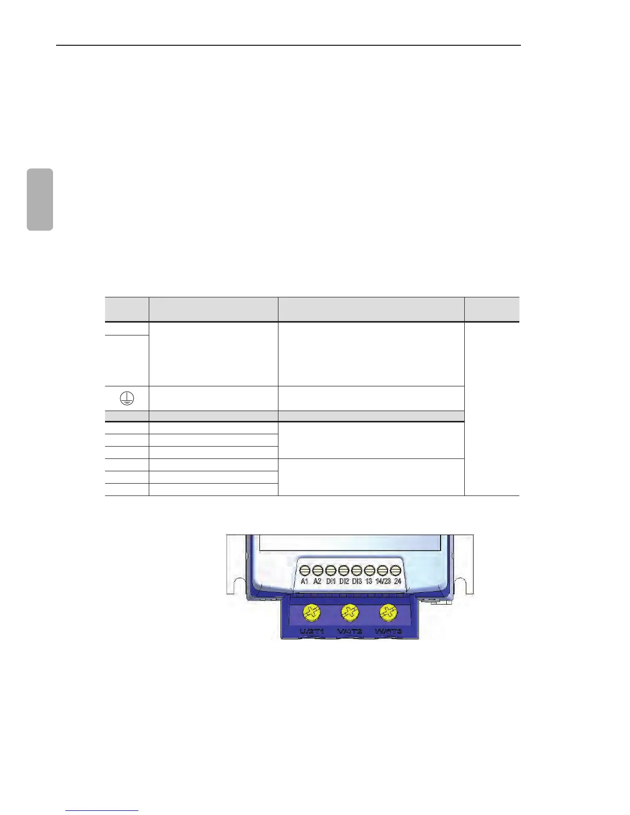
The control connections (digital inputs and relay outputs) are made
throughtheterminals(refertogure3.9).
Terminal Description Specications
Torque Nm
(in lb)
A1
Electronics Supply
Voltage:110to240Vac(-15%to+10%)
(models from 17 A to 200 A)
110 to 130 Vac or 208 to 240 Vac
(-15%to10%)(modelsfrom255A
to 412 A).
0.5 (4.5)
A2
Grounding Only for the 255 to 412 A models
Terminal Factory Default Specications
DI1 Starts/Stops Motor
3 isolated digital inputs
Voltage:110to240Vac(-15%to+10%)
Current:2mAMax.
DI2 Fault reset
DI3 Fault reset
13 Relay 1 output - Operation
Contactcapacity:
Voltage:250Vac
Current:1A
14/23 Relay common point
24 Relay 2 output - Full voltage
Table 3.9 - Description of the control connector pins
Figure 3.9 - Control terminals of the Soft-Starter SSW-07
Some recommended set-ups are shown here and they can be
completely or partly used.
The main warning notes for all the recommended set-ups are
shown below and are described in the schemes by their respective
numbers.