Setting up the printer
2967530000/00/06.202316
6.5 Adjusting the head locking system
The printheads are pressed down by two plungers each
that are positioned in the middle of the head bracket in the
home position. This setting can be retained for most ap-
plications.
The plungers can be adjusted if bright patches occur in the
side margin areas of a print image when using very wide
materials.
Hexagon key
1
2
3
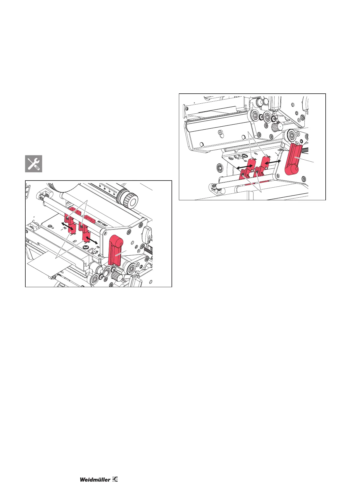
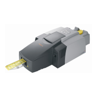
Figure 6.6 Adjusting the top head locking system
► Turn the lever (3) clockwise to lock the top printhead.
► Unscrew the two threaded pins (2) with the hexagon
key.
► Slide the plungers (1) symmetrically to a maximum of
scale value 70.
► Tighten both threaded pins (2).
► Turn the lever (2) counter-clockwise to release the print-
head.
1
2
4
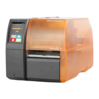
Figure 6.7 Adjusting the bottom head locking system
► Turn the lever (4) counter-clockwise to lock the bottom
printhead.
► Unscrew the two threaded pins (2) with the hexagon
key.
► Slide the plungers (1) symmetrically to a maximum of
scale value 70.
► Tighten both threaded pins (2).
► Turn the lever (2) clockwise to release the printhead.