上海维宏电子科技股份有限公司
SHANGHAI WEIHONG ELECTRONIC TECHNOLOGY CO., LTD.
29 / 116
o Description: DO1 pins are pin No.6 and No.7, which are used for Z-axis
clamping position braking signals.
o Unit: -
o Format: X2X1X0
X2=1: Set DO1 output to the NO contact a. X2=1: Set DO4 output to
the NC contact b.
X1X0=08: Set pin No.6 and No.7 to BK- and BK+ respectively.
o Range: -
o Value: 108
P2-22 Digital output pin DO5 function setting
o Description: DO5 pins are pin No.28 and No.27, which are used for servo
alarm signals.
o Unit: -
o Format: X2X1X0
X2=0: Set DO5 output to the NC contact b.
X1X0=07: Set pin No.28 and No.27 to ALRM+ and ALRM-
respectively.
o Range: -
o Value: 007
3.4.1.2 Set Drive Parameters in Velocity Loop Control Mode
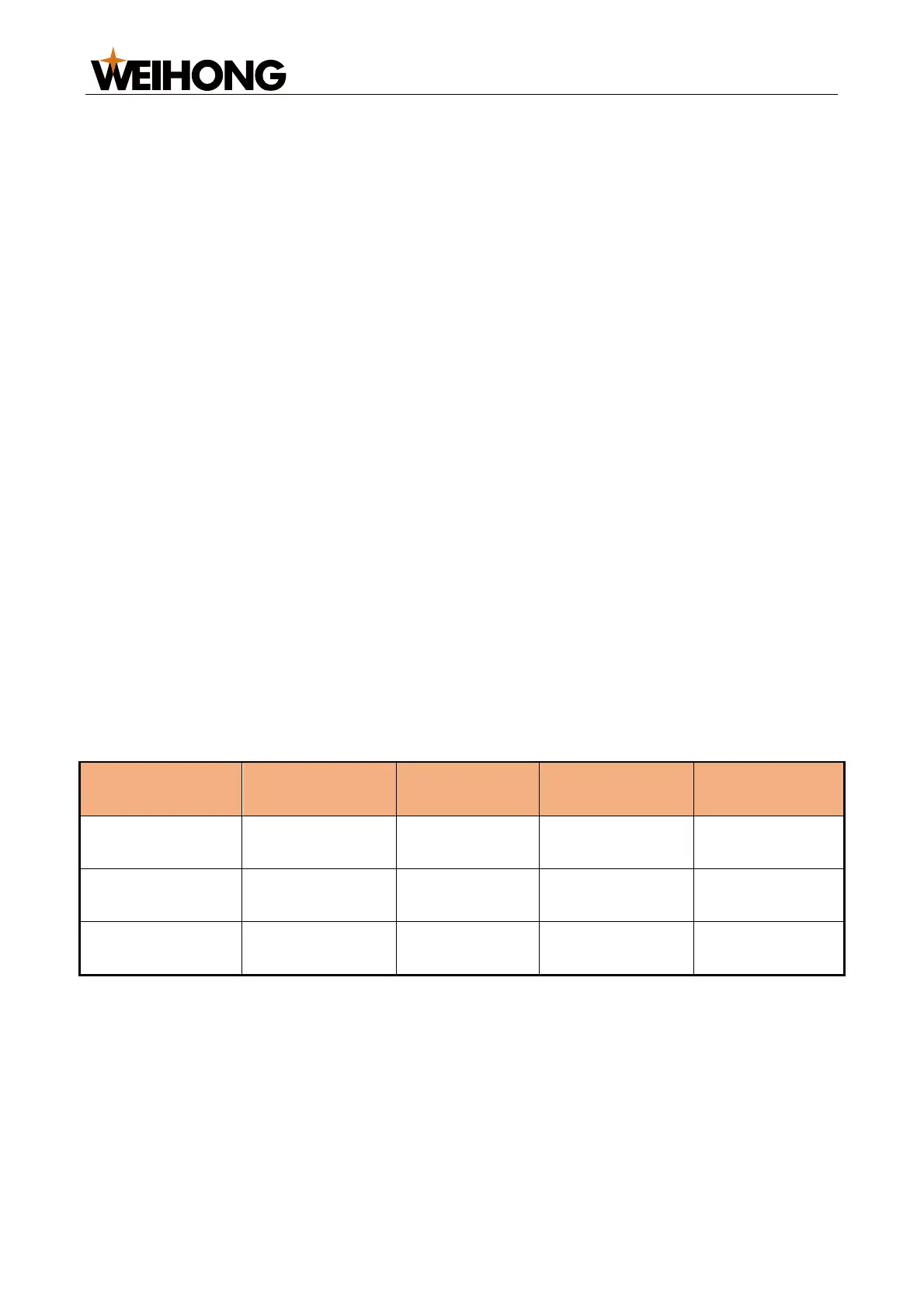
Test parameter settings in velocity loop control mode as shown below:
WISE
Yaskawa Σ- 7
Panasonic MINAS A5
Fuji ALPHA 5
To make the motor output rated rotational speed under 10V voltage in velocity loop control
mode, parameters need to be set differently from that [in position loop control
mode](../topic_ls6000/set_driver_para_en.md#set-drive-parameters-in-position-loop-
control-mode), as shown below (taking a screw pitch of 10 mm as an example):
Motor rotational
speed under 10V
The parameter Motor rotational speed under 10V is available only in velocity loop
control mode.
3.4.2 Set Drive Parameters in Bus Control Systems
Parameter setting methods vary based on the servo drive brand. This section mainly
introduces how to set basic parameters and station addresses of WISE drive and Yaskawa
∑5 / ∑7 drives.
1. [Set Common Drive Parameters](../topic_ls6000/set_driver_para_en.md#set-
common-drive-parameters)