Repairs: Information and Instructions 23
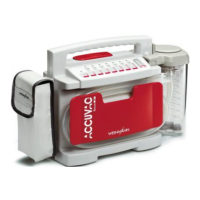
8. Carefully open up cable grip of ribbon cable
connector X5. Then carefully remove ribbon
cable (do not touch the ribbon cable contacts
with your fingers, as this can cause oxidation.)
9. Unscrew 4 retaining screws 46 from the circuit
board.
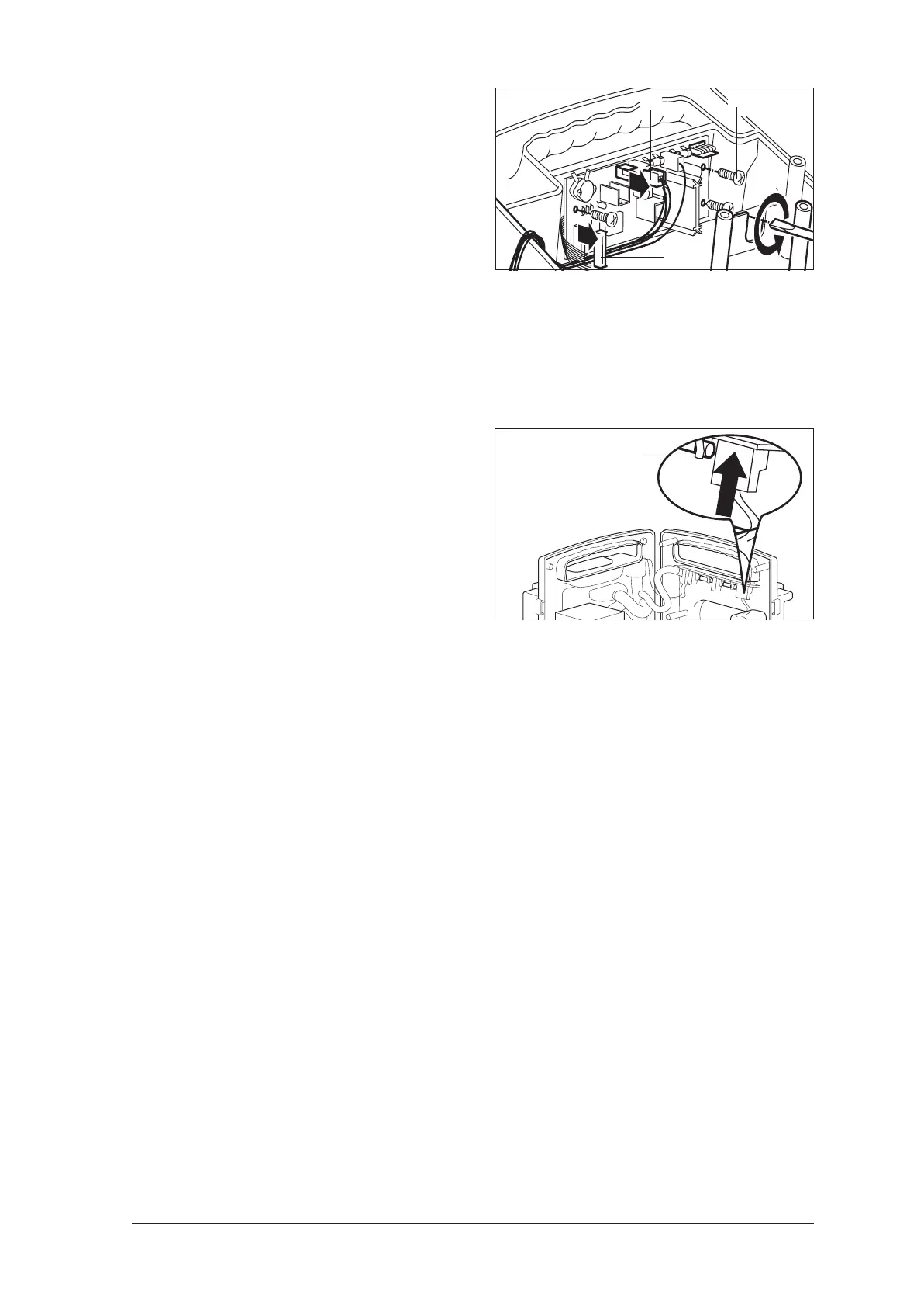
10. Insert the new circuit board in reverse order.
Then route connecting cable so it cannot come
into contact with the pump.
• Attention!
Do not connect electrical power pack
connector X3 yet.
• Wait half a minute to allow the capacitors on the
circuit board to discharge.
11. Carefully connect electrical power pack
connector X3.
12. Close the device (see ”9.3 Closing the de-
vice“ on page 16).
13. Perform initialization (see ”9.7 Initializing the
power pack“ on page 20).
The green 10% LED of the capacity indicator con-
tinues flashing until the electronic control system
has been synchronized with the power pack.
Although the fully charged ACCUVAC Rescue can
be used, the power pack charge status is not dis-
played.
14. Perform a function check (see ”7.2 Performing
the function check“ on page 10).
X5
X4
46
X3
 Loading...