Welch Allyn Model 767
Display Test
The display test begins with each display segment and icon being individually lit in brief and rapid
succession. Immediately after this, all display segments and icons are simultaneously illuminated
briefly followed by a display of the software revision in this instrument. The beeper also briefly sounds
at the beginning of the test. At the end of the test, the display goes blank.
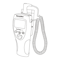
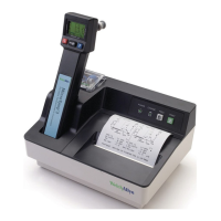
FIGURE 2 - M767 DISPLAY
Note: If a probe is installed during this power up time, the probe type will be displayed as the
last item before the display blanks. At this point, there should be no probe connected to the
instrument.
If there is no display, any missing segments, or no beeper, refer to the Troubleshooting section.
Probe Warmer Circuit Self Tests
Proper instrument functionality should be verified first as described in the Instrument Reset/Self
Tests section (above) before a probe is installed. With a properly functioning instrument, the probe
can be run through the self test. If the instrument is functioning properly and a probe is installed, the
instrument will initiate the probe warmer self test during the instrument reset self test and whenever a
probe is plugged in.
If an instrument has passed the Instrument Reset/Self Tests section, install the probe connector and
observe the display of the probe type. For the M767, the probe type will display for approximately 2
seconds.
· If the display does not show “OrL” or “Aly” with an Oral/Axillary probe plugged in, or “rEC” with a
Rectal probe plugged in, there is a problem with either the probe or the probe connector in the
instrument.
· If the display goes blank after the probe type display, the probe has passed its tests and the
instrument is ready for use. Do not withdraw the probe during this self test.
· If the display shows the malfunction icon |X| and/or the ‘Broken Probe’ icon, refer to the
Troubleshooting section.
Note: Handle the probe only by the probe handle, not the metal shaft. When removing a
probe, disconnect the connector by pressing the locking tab and pulling on the connector
body. Do not pull it by the cord.
If there are any problems with probe initialization, refer to the Troubleshooting section.
 Loading...