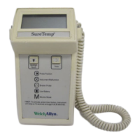
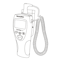
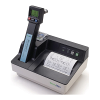
Welch Allyn Model 767
Internal E5.2 Heater watchdog timeout test.
Internal E6.0 PTB resistor “temperature” test.
Note: Error codes E0.1, E0.2, E0.3, can sometimes be caused by a faulty probe. It is advisable to
remove the probe completely from the instrument and check its functionality as described in the
Operational Characteristics section before assuming an instrument problem instead of a probe
problem. If another probe is available, this can prove useful in tracking down the source of the
problem.
Equipment Required
Most operations can be performed with standard tools and meters. A 4” long Torx, T-8, driver is
needed for most screws. A #1 Phillips screwdriver is needed for the probe switch screws.
A standard lab 3.5 digit digital multi-meter (DMM) will provide sufficient accuracy for a host of tests. A
needle tipped pair of probes is recommended.
For particularly difficult tasks, a digital storage oscilloscope is sometimes the only way to analyze high
speed signals, but is not generally required.
Standard electronics tools and supplies for small surface mounted and through hole component
rework will be needed to perform any electronics repairs. Some surface mounted components are
extremely small and present a challenge for rework by hand. A light touch, tweezers, sharp soldering
iron tip (#7) and low heat is recommended.
Note: Normal ESD precautions must be observed.
A Model 767 Wall Transformer is recommended for use as a power supply. Power and ground are
available at J7 and J8, respectively.
Terminology
Many standard abbreviations are used in this section (and elsewhere):
PCB printed circuit board (the board itself) LCD PCB PCB holding the display assembly
PCA printed circuit assembly (the board with all its
components)
DMM Digital Multi-Meter
Main PCB large PCB holding the microprocessor O-Scope Oscilloscope
LCD Liquid Crystal Display
Component Reference Designators:
C capacitor Q transistor
D diode R resistor
E test point S switch
J connector jack T transformer
L inductor U integrated circuit
P connector plug X crystal, resonator
 Loading...