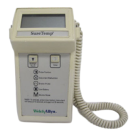
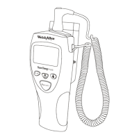
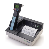
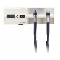
Welch Allyn Model 767
· When J1-3 (CAL) is connected to J1-5 (GND), but J1-6 (RCTL) is not connected to J1-5 (GND),
the software determines that the probe is Rectal probe;
· When J1-6 (RCTL) is connected to J1-5 (GND), but J1-3 (CAL) is not connected to J1-5 (GND),
the software determines that the probe is a Calibration Key;
· When neither J1-3 (CAL) or J1-6 (RCTL) are connected to J1-5 (GND), the software
determines that no probe has been plugged in.
C19 and C20, both 0.01 uF capacitors, are bypass capacitors used to filter out
spurious noise to the microprocessor on the probe input lines J1-6(PROBE_1) and
J1-3(PROBE_0).
Reset/Self Tests
Upon power up, (assuming that the electronics have been discharged sufficiently by turning off power
to the 767 Wall Transformer Unit for at least 1 second) the microprocessor receives a power up reset
signal from the components associated with the reset line at U1-12. When power is applied to the
instrument, U4 (Econo reset chip) waits approximately 200 milli-seconds before providing an active
low reset to the microprocessor.
When the reset signal is complete, the microprocessor launches a series of self checks which include
RAM test, ROM test, instruction set test, self calibration tests (electronics accuracy test, hi cal, low
cal), probe warmer circuitry tests, probe test, and ambient temperature test. Any failures here will
cause a specific error code to be displayed to assist with debugging.
Power Supply
Power is drawn from an 8VAC power supply. This AC voltage is converted to DC by a full wave
bridge rectifier (D7, D8, D9, and D10), regulated by a low dropout 5 volt regulator (U3), and filtered by
capacitors (C18, C24, C30, C28, C29 and C13). The regulated voltage will range from about 4.75
volts to 5.25 volts DC. This +5VDC (VDD) is further filtered to create an analog +5 volt branch (VCC).
Other Components
Microcontroller
A NEC UPD78064 or UPD78063 single chip microcontroller in a QFP package (U1) is used for signal
digitizing, data processing, program memory addressing and storage, and I/O interfacing. The
microcontroller also includes an LCD controller/driver which allows internal conversion of CMOS logic
levels to a data format capable of driving the Model 767 LCD. In this application, the microcontroller is
running at approximately 2.5 MHz, which is achieved by using a 4.9152 MHz Crystal (X1).
Microprocessor Clock
The clock for the microprocessor is generated by X1 and capacitors C26 and C27, which form a
4.9152 MHz. oscillator circuit. The microcontroller is running at approximately 2.5 MHz, which is
achieved by internally dividing the frequency of oscillation by two.
 Loading...