English
Installation and operating instructions Wilo-Drain TS 50, TS 65, TP 50, TP 65 33
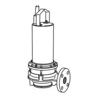
nection. Semi-open, single-channel or free-flow
impellers are used.
The product is not self-suctioning which means
that the pumped liquid must flow in on its own.
4.2.2 Motor
The motor is a dry run motor and made of stainless
steel. The motor is cooled by the pumped liquid and
the heat is transferred via the motor housing to the
surrounding fluid. The unit must therefore always be
submerged when operated. It can be used continu-
ously or in intervals.
Furthermore, the motor is equipped with a thermal
motor monitor (WSK). This protects the motor winding
from overheating. On the units TS 50 (1~230 V/50 Hz),
it is integrated and self-switching. This means that the
motor is switched off when it overheats and automati-
cally switched back on after it cools down.
The connection cable is available in different versions:
• With free cable end
• Version "A" for 1~230 V/50 Hz with float switch, capac-
itor box and Schuko plug
• Version "A" for 3~400 V/50 Hz with float switch and
CEE plug
• Version "CEE" with CEE plug
Note the IP protection class of the CEE plug.
4.2.3 Sealing
The sealing to the pumped liquid and to the motor
compartment depends on the type:
• TS 50…/TS 65…: With a mechanical shaft seal on the
liquid side, with a rotary shaft seal on the motor side
• TP 50…/TS 65…: With a mechanical shaft seal on the
liquid side, with a rotary shaft seal on the motor side
The sealing chamber between the seals is filled with
medicinal white oil. The sealing chamber is fully filled
with white oil when the product is assembled.
4.2.4 Float switch
With the "A" version, the float switch is connected to
the capacitor box / CEE plug.
The float switch makes it possible to set up a level-
control system which switches the unit on and off
automatically.
4.3 Explosion protection in accordance with ATEX
The motors are certified for use in environments where
explosions may occur, in accordance with directive
94/09/EC, and which require electrical devices in device
group II, category 2.
The motors can be used in both zone 1 and zone 2.
These motors may not be used in zone 0!
Non-electrical devices (e.g. hydraulics) also comply
with EC directive 94/09/EC.
4.3.1 Explosion coding
The Ex d IIB T4 explosion coding on the type plate indi-
cates the following:
• Ex = explosion-proof device complying to Euro norm
• d = ignition protection type for motor casing: Pressure-
resistant encapsulation
• II = intended for places where explosions may occur,
with the exception of mines
• B = intended for use with gases in sub-group B (all
gases excluding hydrogen, acetylene, carbon disul-
phide)
• T4 = max. surface temperature of the device is 275 °F
(135°C)
4.3.2 "Pressure-resistant encapsulation" protection type
Motors with this protection type are equipped with a
temperature control system.
The temperature control system should be con-
nected in such a manner that, if the temperature
limiter is triggered, it can only be switched back
on after the release button has been manually
activated.
4.4 Explosion protection certification number
• TS 50… (3~400 V/50 Hz): LCIE 03 ATEX 6202
• TS 65…: LCIE 03 ATEX 6202
• TP 65…: LCIE 03 ATEX 6202
4.5 Operating modes
4.5.1 Operating mode “S1” (continuous operation)
The pump can operate continuously at the rated load
without exceeding the maximum permissible tempera-
ture.
4.5.2 Operating mode "S2" (short-term operation)
The maximum operating period is given in minutes, for
example, S2-15. The pause must continue until the
machine temperature no longer deviates from that of
the coolant by more than 2 K .
4.5.3 Operating mode S3 (interval operation)
This operating mode defines a combination of periods
of operation and standstill. With S3 operation, the val-
ues given are always calculated based on a period of
10 minutes.
Examples
• S3 20%
Operation 20% of 10 min ) 2 min/standstill 80% of
10 min = 8 min
Beware of static electricity!
Static electricity may be produced with plastic
materials. This can give you an electric shock.
Danger of explosion!
The housing of the hydraulics must be fully
flooded (completely filled with the pumped liq-
uid) during operation. If the housing is not sub-
merged and/or there is air in the hydraulics, flying
sparks may cause an explosion e.g. due to static
charge! Ensure that dry-run protection is in place
for switching off.
 Loading...