Maintenance1132−2/A1
RT-flex58T-E
Winterthur Gas & Diesel Ltd.
8/ 14
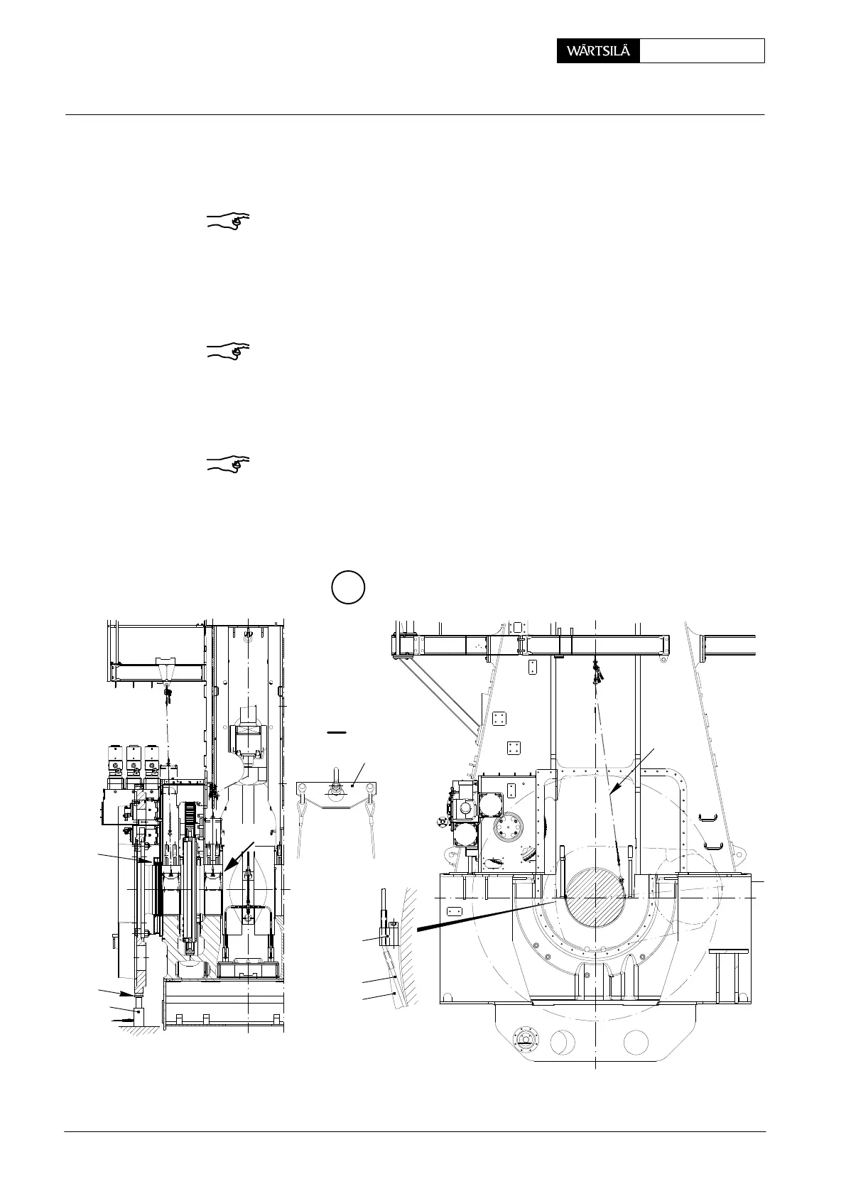
4.4 Turning out main bearing shell No. 1
D Crankshaft lifted up by approx. 0.2 mm (see paragraphs 5.1 and 5.2).
Remark: Turning-out device 94118 must only be fitted to bearing shell No. 1
instead of turning-out device 94118A, which is provided for all other bearing shells.
⇒ Fasten manual ratchet ’H1’ with rope 94120B to gallery support.
⇒ Fasten turning-out device 94118 to bearing shell 3 using screwdriver 94129,
lead ropes ’a’ along the lateral edges of the bearing shell 3 to the other side
and connect them with lifting yoke 94119.
Remark: By means of a wire attached to the ropes they can be pulled below the
bearing journal to the other side.
⇒ Slowly turn out bearing shell using manual ratchet ’H1’ from the bearing girder
until both ends of the bearing shell are free (no meshing), check!
⇒ Remove lifting yoke.
Remark: If a bearing shell jams during turning out, lifting yoke 94119 must be fas-
tened to the two opposite wire ropes of turning-out device 94118. Subsequently
draw the bearing shell back to the initial position until the bearing shell is freed.
K
II
94119
94120B
H1
94118
H1
WCH01015
II
3
a
PR
PR
94959
Removal and Fitting of a Main Bearing
2013 / V2