Maintenance1132−2/A1
RT-flex58T-E
Winterthur Gas & Diesel Ltd.
6/ 14
4. Turning out and removal of lower main bearing shell
Attention! Never remove two neighbouring bearing shells at the same time!
The removing procedure for a lower bearing shell 3 (Fig. ’A’) is the same for all main
bearings with the exception of main bearing No. 1 at the driving end.
D For the removal of bearing shells No. 1 and 2 the flywheel must additionally be
pressed up with hydraulic ram 94950. To protect the flywheel toothing, put a
copper or aluminium plate between the ram and the flywheel (Fig. ’K’).
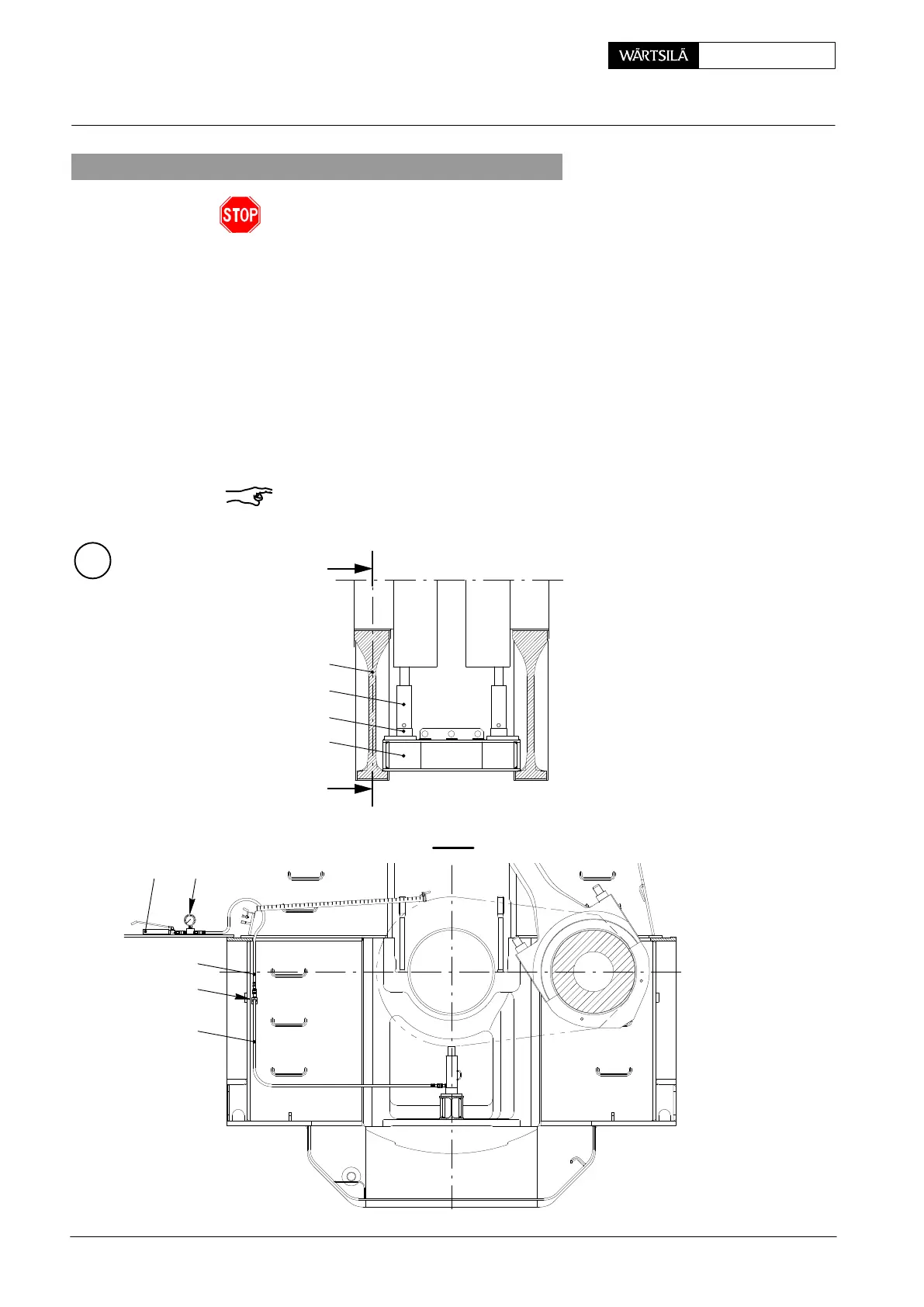
4.1 Placing of hydraulic jacks
⇒ Turn corresponding crank to exhaust side approx. 90_ after T.D.C.
⇒ Put support 94141 on two bearing girders 6 parallel to the engine axis.
⇒ Place hydraulic jacks 94936 on support 94141.
⇒ Connect the hydraulic jacks with HP hoses 94935 and 94935A, as well as
hydr. distributor 94934A to HP oil pump 94931.
Remark: Depending on hydraulic jacks 94936, ground plates 94141A must be
placed onto support 94141 in order to reach the height necessary to lift the crank-
shaft.
H
I - I
9493294931
018.178/09
94935
94935A
94934A
I
I
94936
94141
94141A
6
Removal and Fitting of a Main Bearing
2013