10
• Place the thermostat on an inner wall free from
draught.
• Never place the thermostat within the throw of the
heater.
• Never mount the thermostat near the aerials of
internal communication networks. These emit
radiation that can disturb the thermostat. Keep
several meters distance.
In all cases, the communication between the heater
and the thermostat is based on a two wire, low-voltage
connection. (see the electrical wiring diagram in §11).
Follow these instructions to prevent malfunction of the
installation and damage to the thermostat or air heater:
• Use a cable with the following specifications:
– Signal cable.
– Shielded and twisted.
– Minimum dimensions: 1 x 2 x Ø0,8 mm
2
.
– Maximum length: 200 m.
CAUTION! Keep the thermostat cable separated from the
mains cables.
CAUTION! Connect the cable’s earth shield only to the
earth terminal inside the air heater. Do not connect the
other end of the cable’s earth shield.
NOTICE A cable with a thickness of less than 0.8 mm will
result in a poor signal.
NOTICE A cable that is not shielded and twisted may
result in a disturbed communication in an EMC-unfriendly
environment.
4.5.2 Modulating room thermostat installation
To connect the air heater to an MTS or MTC thermostat, do
the following:
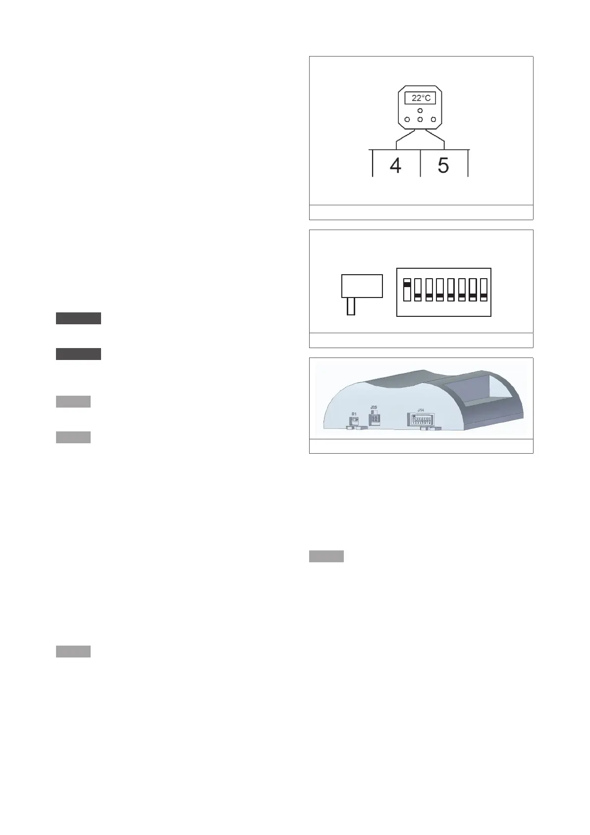
1. Connect the two control wires to terminals 4 and
5 (see figure 9 or the electrical wiring diagram in
§11).
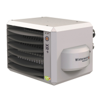
a. Set the S1 and J14 switches on the control
unit as follows (figure 10/11):
b. Set S1 to 1.
c. Set J14 to 1.
NOTICE The air heater must be switched o when setting
the switches. Otherwise the settings will have no eect.
Figure 9 - Modulating thermostat connection
1 2 3 4 5 6 7 8
ON
1 0
S1
J14
Figure 10 - Positions of the S1 and J14 switches
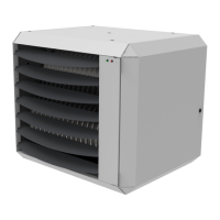
Figure 11 - Location of the S1 and J14 switches
4.5.3 Installation of multiple heaters on one control unit
An MTC or MTS room thermostat, or interface module can
control up to 8 air heaters. To connect the air heaters, do
the following (figure 12):
NOTICE This functionality does not apply to an ON/OFF
thermostat.
1. Connect the two wires of the thermostat to termi-
nals 4 and 5 of the first air heater.
2. Connect the first air heater to the second air heater.
3. Repeat for each subsequent air heater.