3064458_201811
39
17. Parameter description
Important information:
In these schematic diagrams, shut-off valves, air vent valves and safety equipment are not fully represented.
These should be provided subject to the individual system, in line with the applicable standards and regulations.
Hydraulic and electrical data can be found in the Hydraulic System Solutions technical guide.
In DHW mode, the pump runs at this set value. Independent of the pump control type
set in H37.
Parameter H41
Feed/heating circuit pump speed,
DHW
Factory setting: see table
Setting range: 15 to 100 %
Individual setting:_____
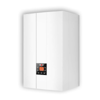
Systemconguration60
Cascade (automatic setting if cascade
module is connected)
• eBus address H10 must be set for each
condensing boiler
• Burner starts following a demand from the cascade
module via eBus
(0-100 % burner output; min. to max. within the
programmed limits H02 and H04)
• Internal appliance pump is enabled as a feed pump
• Header temperature control via cascade module
• Automatic output reduction when approaching TV
max
(H08)
is enabled. Shutdown when TV
max
is reached
• A low loss header or plate heat exchanger can be used to
provide hydraulic separation.
eBus
SAF
KM
H10 = 1 H10 = 2
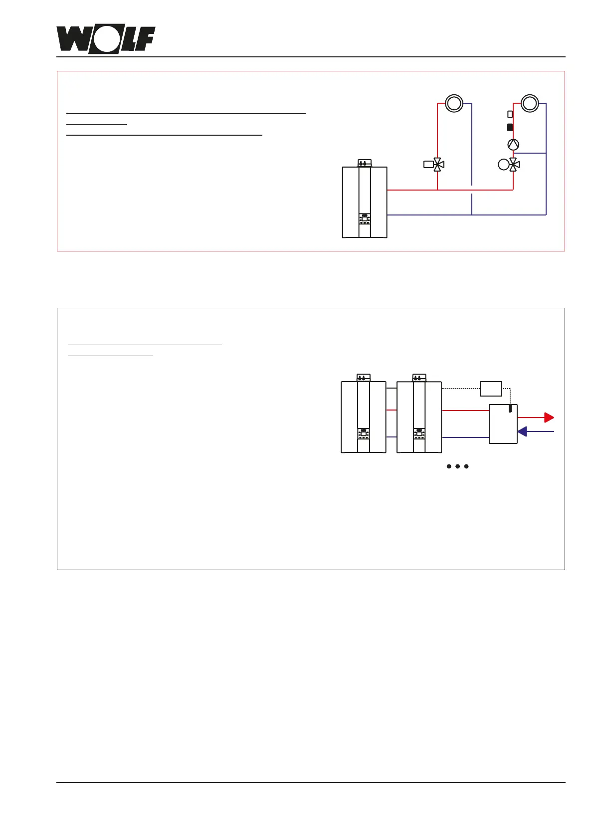
Systemconguration02
Direct heating circuit and one or more circuits with mixer via
mixer modules
(no direct heating circuit at the condensing boiler)
• Burner starts subject to demand from the connected
circuits with mixer
• Internal appliance pump is enabled as a feed pump
• Thermostatic boiler control;
set value is specied by circuits with mixer
HK MK1
M