3064458_201811
57
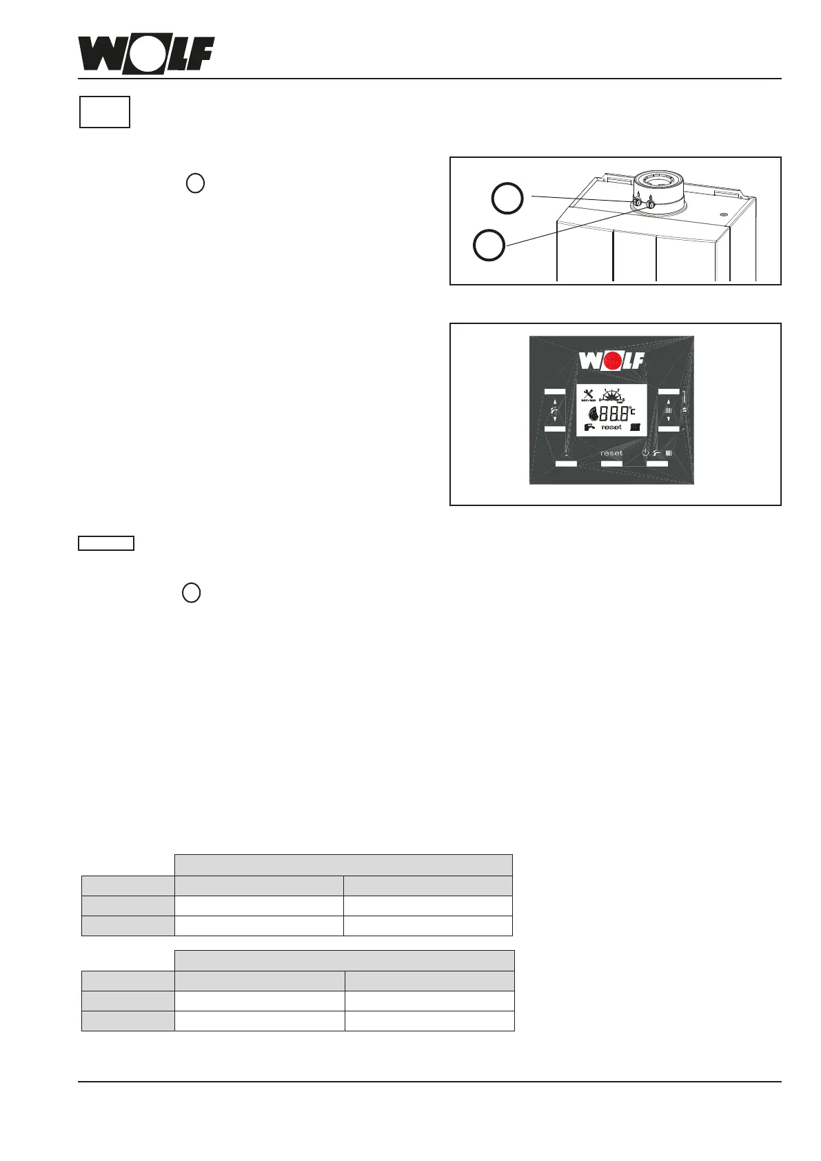
Fig: Checking the ue gas parameters
Checking the intake air
1. Remove screw A from the left hand test port.
2. Open the gas ball valve.
3. Insert the test probe.
4. Switch ON the boiler and enable the emissions test
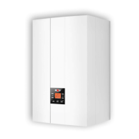
mode via buttons 6 and 7 (press and hold for 5 s).
5. Check the temperature and CO
2
.
6. In the case of a balanced ue, the ue is not gas-tight if
the CO
2
content is > 0.3 %. The leak must be rectied.
7. After the test has been completed, switch the boiler OFF,
remove the test probe and close the test port. Ensure
the screws are tightly secured.
Checkingtheuegasparameters
When the test port is open, ue gas can escape
into the installation room. There is a risk of
asphyxiation.
1. Remove screw B from the right hand test port.
2. Open the gas ball valve.
3. Insert the test probe.
4. Switch ON the boiler and enable the emissions test
mode via buttons 6 and 7 (press and hold for 5 s).
5. Carry out the checks after a minimum of 20 s of
operation, measuring rst at upper load and then at
lower load.
6. Flue gas values (for permissible values, see table)
7. After the test has been completed, switch the boiler OFF,
remove the test probe and close the test port. Ensure
the screws / gasket are tight / seated rmly.
Please note
1
2
4
6
7
Fig: Control unit buttons
5
FGB / FGB-K appliance closed at upper load
Gas type
CO
2
in % O
2
in %
Natural gas E/H/L
9.3 % ± 0.2 % 4.2 ± 0.3 %
LPG P 10.5 % ± 0.2 % 4.9 ± 0.3 %
FGB / FGB-K appliance closed at lower load
Gas type
CO
2
in % O
2
in %
Natural gas E/H/L
9,1 % ± 0.2 % 4,7 ± 0.3 %
LPG P 10.0 % ± 0.2 % 5.7 ± 0.3 %
Table: Flue gas parameters
A
B
Flue gas test port
Intake air test port
25. Checking the combustion
parameters
A ue gas emissions test by a contractor is necessary after every modication of the components, including the
control unit PCB, fan, mixing device, burner and gas valve.
Test the combustion parameters with the appliance closed.
Please
note