Manual 26833 TecJet 52 Gen II
Woodward 15
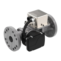
Figure 2-1b. Allowable Actuator Orientations
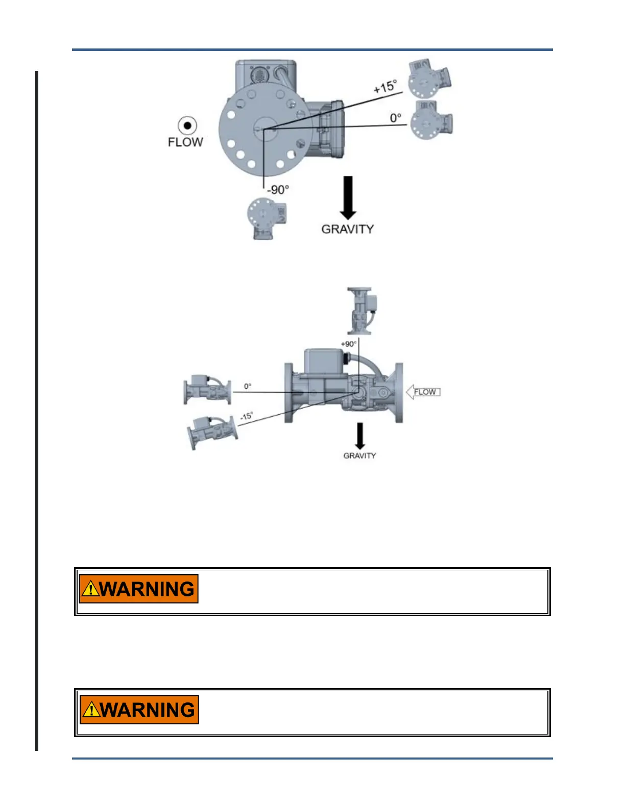
Figure 2-1c. Allowable Bore Orientations
For on-engine applications, a suitable bracket must be constructed to support the weight of the valve on
the engine. See the outline drawing (Figure 2-2) for the valve mounting feet hole and hole-location details.
An optional mounting bracket is available to provide a base mounting to the TecJet (Figure 2-3). All
mounting configurations should ensure that moment loads are not applied either through installation or
thermal stress that could cause the valve to bind and lose functionality.
The TecJet 52 is not intended to support the inlet or outlet piping.
Suitable brackets must be constructed to support the valve and
piping separately to prevent damage to the TecJet.
The inlet and outlet piping of the TecJet 52 must be in accordance with ANSI/ISA-S75.02 to ensure the
flow metering accuracy specified elsewhere in this manual. However, an inlet piping length as short as 6
diameters and an outlet piping length as short as 2 diameters can typically be used with a negligible loss
in valve metering accuracy.
EXPLOSION HAZARD—Leak check all gaseous fuel connections.
Leaking gaseous fuel can cause explosion hazards, property
damage, or loss of life.
 Loading...