Manual 26833 TecJet 52 Gen II
Woodward 22
CAN Hi In
CAN Lo In
CAN Shield
CAN Hi Out
CAN Lo Out
PWM In +
Keyswitch
Power In+
Power In -
TecJet
Jumper for CAN Termination Resistor
Z
W
F
L
K
B
A
Q
P
U
T
X
S
R
PWM In -
4-20mA Analog In +
4-20mA Analog In -
}
}
From Previous
CAN Device
To Next CAN
Device
Battery
E
Status Output (Discrete)
H
J
Discrete/RS232 Common
V
CAN Gnd
Y PWM Shield
G
RS232 Serial
Communication
CAN ID2
CAN ID1
N
M
D
C
Aux. Power Out
Aux. Power Out
Load (relay
coil or
lamp)
1
1
1
3
TTL
232
3
RS232 Tx
RS232 Rx
2
5
TTL to RS 232 Converter
(Woodward 1249-1039)
2
Straight-Through
9-Pin Serial Cable
(Must have all conductors)
NOTES:
2
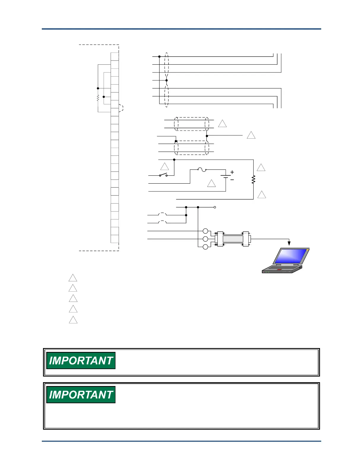
USE AUX. POWER OUT (PINS C OR D) TO POWER THE KEYSWITCH INPUT AND THE STATUS OUTPUT LOAD,
WHEN NEEDED.
3
THE STATUS OUTPUT IS A LOW-SIDE SWITCH THAT CAN BE OPERATED AT A MAXIMUM OF 42 V AND 500 MA.
THE MINIMUM WIRE SIZE FOR PINS W AND Z (POWER SUPPLY INPUTS) IS 16 AWG. FOR ALL OTHER I/O, THE
RECOMMENDED WIRE SIZE IS AT LEAST 18 AWG.
SHIELDING FOR THE ANALOG INPUT IS OPTIONAL
4
4
5
5
THE SHIELDING FOR THE ANALOG INPUT (OPTIONAL) AND FOR THE PWM INPUT SHOULD BE TERMINATED AT
THE CUSTOMER END.
Figure 2-5. TecJet 52 Wiring Diagram
All signal and I/O wiring on the TecJet 52 is not to exceed 30 m (100
ft) in length. See “Supply Voltage” section for specific wire length
limitations on the power supply inputs.
When wiring to pins V and/or J on the TecJet 52, be careful to ensure
that the external circuit interface is isolated from battery ground,
either by means of galvanic isolation or differential input/output.
If it is not, a ground loop could be formed that can cause excess
noise on the lines and/or damage to circuits.
 Loading...