INSTALLATION
6 720 803 599 (2012/06)22
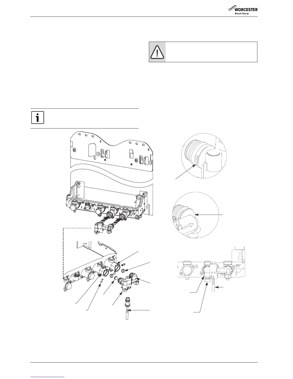
4.3 CHARGING LINK (FILLING LOOP)
B Fully close the isolating valves on both the cold water inlet and CH
return connections.
B Check that the gas and water connections are tight.
1. Unscrew the blanking plugs from both the cold water inlet and CH
return connections.
B Place the filter inside the inlet side of the Charging Link ensuring that
the filter mesh is inside the inlet.
B Fit the Charging Link assembly onto the cold water inlet and CH return
connections.
B Do not insert the Charging Key at this stage.
2. Ensure that the Charging Link is pushed in fully to the stop tabs on
both sides of the Charging Link.
B Fit two M4 screws complete with washers to each of the two
connections.
B Do not attempt to turn the brass hexagon connectors.
B Ensure that the white plastic control tap on the Charging Link is turned
fully into its closed position, see diagram 3.
B Open the isolating valves on both the cold water inlet and CH return
connections.
B Insert the Charging Key initially aligning the arrow on the key with the
“unlock” symbol on the Charging Link body. Ensure that the key is
inserted fully and turn to the “lock” position. Check that the key is
secure, see diagram 3 below.
B To fill the system from the cold water inlet turn the white plastic
control tap on the Charging Link to the fully out position.
B Once the system has been filled turn the white Control Tap to its
closed position and then remove the Charging Key by turning back to
its “unlock” position and withdrawing. Store the Charging Key in the
clip provided on the inside of the bottom panel.
Fig. 22 Fitting the charging link
It is not possible to access the third screw hole so this
can be left.
NOTICE: Only proceed further and fill the boiler and
system once the boiler is fitted and all connections are
water tight
Tab
Tab
2
1.
Charging Key
M4 Screw
and Washer
White
Control
Tap
3
6720647361-09.2Wo
Blanking Plug
Charging Key
Charging Link
Assembly
Filter
M4 Screw
and Washer
DCW Inlet
Connection
CH Return Connection
White
Control
Tap

 Loading...