INSTALLATION
6 720 803 599 (2012/06)26
4.6.4 INSTALLING THE STANDARD FLUE
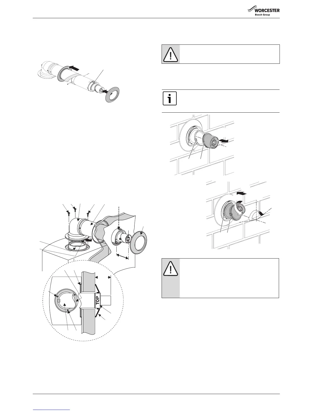
1. Set the flue length to the distance required, secure with screw and
seal joint with the aluminium tape supplied.
Slide the inner wall seal (1) onto the terminal (2) as shown.
If fitting from inside the building; slide the outer wall seal (3) onto the
terminal (2) as shown.
Fig. 30 Telescopic flue
2. Remove the three screws (4, 8) around the flue outlet (6) on the
boiler. See screw pack in boiler.
Check the boiler flue seal is correctly seated.
Apply silicone grease to the boiler flue seal.
3. Position terminal (2) through the flue opening in the wall to the
outside of the building by the distance shown.
The flue terminal MUST be fitted with the 'TOP' uppermost to allow
the correct fit and use of the plume management system.
4. Align the flue turret (5) to the boiler flue outlet (6) with flat (7) facing
to the rear of the boiler.
Push the flue turret (5) straight down into the boiler flue outlet (6).
For ease of assembly, locate screw (8) first and then fit screws (4) to
secure flue turret (5).
If fitting from the outside of the building; slide the outer wall seal (3)
onto the terminal (2) as shown.
Fig. 31 Flue installation
4.6.5 FLUE TERMINAL PLUME RE-DIRECTION:
The flue discharge can be re-directed allowing some plume redirection
control, alternatively, a complete plume management system can be
fitted to the flue terminal.
RE-DIRECTING THE FLUE DISCHARGE
1. Using a suitable tool, release the clips (1 & 2) the terminal end and
rotate through 180°.
1. Refit to the terminal, ensuring that the clips (1 & 2) are engaged and
secure.
2. Loosen screws (3) and rotate the entire outlet assembly to redirect
the plume. Tighten screws (3) to secure in the required position.
Fig. 32 Plume redirection
3.
4.
1.
1.
2.
TOP
6720644842-08.1Wo
TOP
4
5
6
4
110mm
7
4.
3.
2.
2
110mm
3
8
7
2
1
5
TOP
VIEW
8
4
3
6720647361-17.1Wo
NOTICE: DO NOT rotate the complete terminal
assembly.
The flue terminal outlet has built-in stops to limit rotation
for horizontal flues to allow condensate to run back into
the boiler for safe disposal. Do not attempt to force
beyond the limit stops.
NOTICE: Outlet position
B The flue terminal outlet position must follow those
stated in the relevant appliance instruction manual.
When redirecting the flue discharge the outlet
terminal must be at least 1500mm from any opening
in the direction of the discharge to prevent
combustion products from entering the building.
1
2
1.
3.
2.
3
1
±80°
180°
6720643895-34.1Wo

 Loading...