SERVICING AND SPARES
6 720 803 599 (2012/06)42
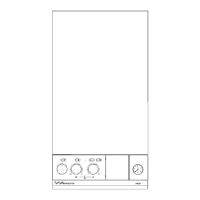
12. FAN ASSEMBLY
B Remove electrical connector from fan.
B Remove condensate trap (see page 37).
1. Undo the union connection (A) from the top of the gas valve.
B Remove wire clip (B) from air/gas adjustment assembly (C) then pull
gas pipe down.
2. Unscrew two screws (D).
3. Remove fan from boiler.
4. Remove three screws retaining the air/gas adjustment assembly (E).
B Reassemble with new fan ensuring that seals are correctly fitted.
Fig. 59 Fan assembly removal
13. ELECTRODE ASSEMBLY
B Disconnect spark electrodes and flame sensor connection.
B Remove two screws (F).
B Remove spark/flame electrode assembly (G) from heat exchanger.
B Inspect the spark/flame electrode assembly and ceramics for signs of
contamination or damage, replace as necessary.
B If necessary, clean the spark/flame electrode assembly with a plastic
scouring pad.
B Replace electrode gasket and heatshield.
B Re-assemble with the new gasket and secure with the screws (F)
removed earlier.
Fig. 60 Electrode assembly
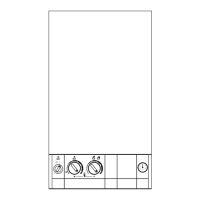
14. AIR/GAS MANIFOLD
1. Remove cover panel (A) by removing screws (B).
B Check that the boiler is completely isolated from the gas supply.
Fig. 61 Top panel
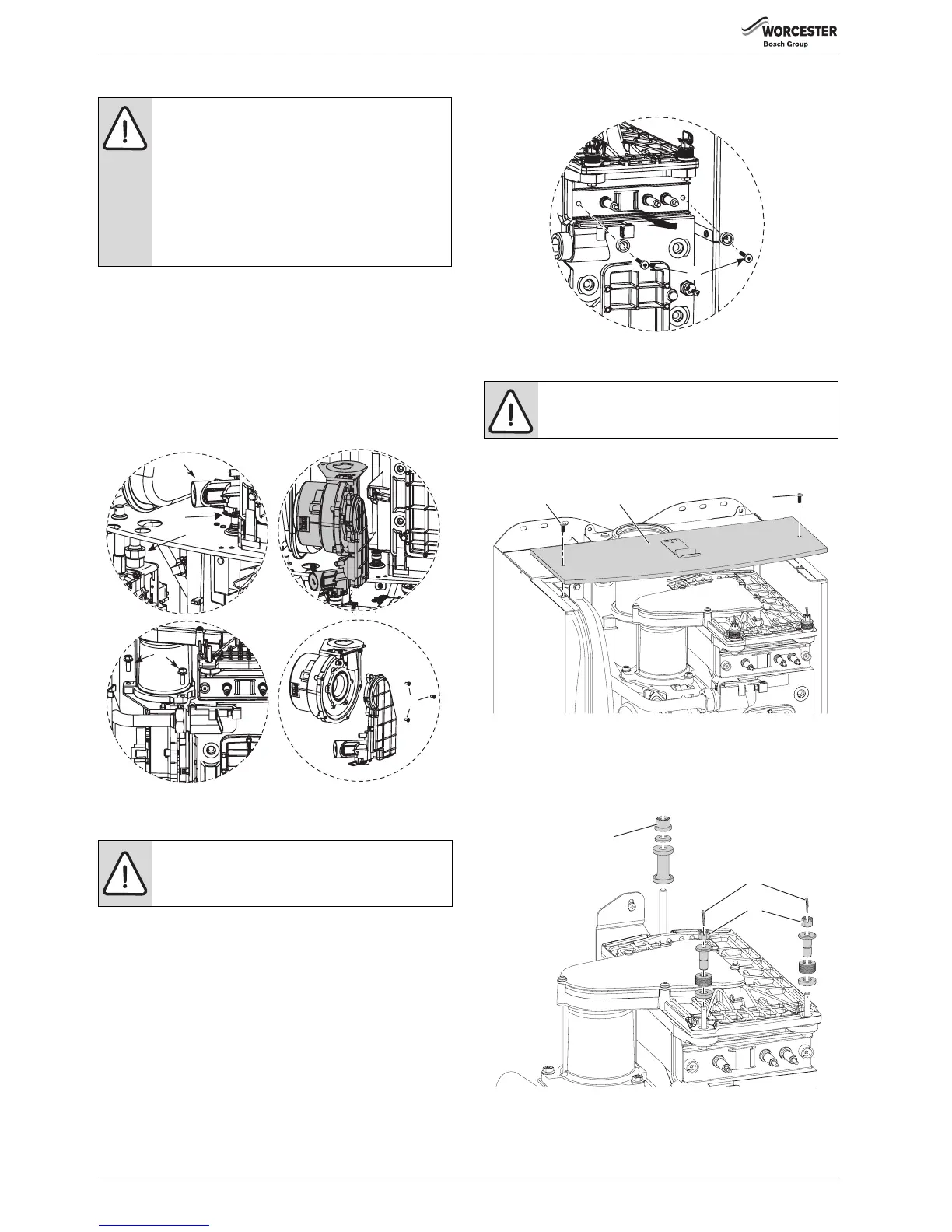
2. Remove clips (C) and unscrew the two bolts (D).
B Unscrew and remove the two hexagon screws (E) securing the fan.
B Slacken fully the rear securing bolt (F).
Fig. 62 Release air/gas manifold
NOTICE: Air/Gas ratio
B After re-assembly the combustion must be checked
using the procedure in the section “Setting the air/gas
ratio.”
B The setting of the gas ratio must be carried out by a
competent person.
Setting the air/gas ratio must not be attempted unless
the person carrying out the operation is equipped
with a combustion analyser conforming to BS 7927
and is competent in its use.
WARNING: Electrode gasket
B Do not remove the electrode assembly unless a new
gasket and heatshield are available for re-assembly.
B
C
A
D
2.
1.
6720647361-37.2Wo
E

 Loading...