Inspection and maintenance
Greenstar 4000 – 6 720 891 161 (2020/09)
60
It is recommended to use the cleaning tool accessory, comprising of
brush and lifting tool to assist in cleaning the heat exchanger assembly.
Part number 7 733 600 091.
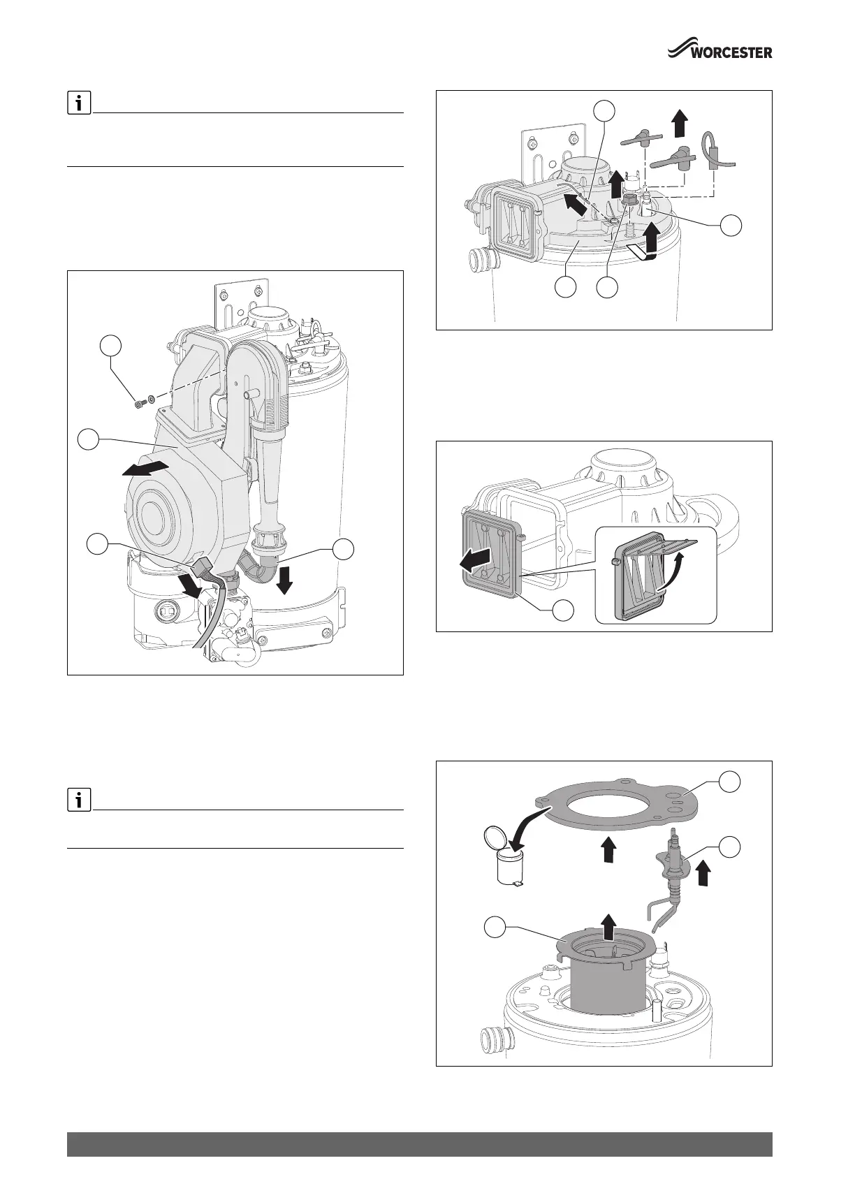
Refer to figure 71.
▶ Disconnect the electrical connection [3] from the fan.
▶ Remove the gas hose [2] from the venturi nozzle.
▶ Remove the screw [1] on the mixing device.
▶ Remove the fan with mixing device [4].
Fig. 71 Removing the fan with mixing unit
Refer to figure 72.
▶ Pull off cables from the electrode set [2].
▶ Pull off cable [1].
▶ Remove M8 nut [3].
▶ Remove the burner cover [4].
On re-assembly, to ensure a full gas tight seal, tighten the M8 nut down
firmly, without over tightening.
Fig. 72 Remove the burner cover
Refer to figure 73.
▶ Remove the non-return valve (bearing plate)[1].
– Check for damage/cracks or deformation and for contamination,
replace if required.
– Ensure non-return valve moves freely.
Fig. 73 Non-return valve (bearing plate) in the mixing unit
Refer to figure 74.
▶ Remove the gasket.
▶ Remove electrode set [2].
– Check for damage or deformation, replace if required.
– Check electrodes for contamination, clean or replace, if required.
▶ Remove the burner [3].
Fig. 74 Removing the burner
0010036060-001
3
4
2
1
0010036061-001
1
0010034247-001
3
1
2
 Loading...


