SERVICE AND SPARES
Greenstar Si Compact
ErP
- 6 720 813 278 (2015/07) 45
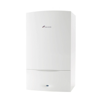
Fig. 73 Heat exchanger cleaning tool
To clean the front channel of the heat exchanger
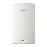
3. Orient the cleaning tool (2) as shown in figure 74 and insert the tool
into the front channel for cleaning.
4. Move the cleaning tool handle in an up and down motion, using the
front edge of the heat exchanger as a pivot, to clean the channel.
▶ Use the brush to dislodge the debris and pour water down the
channels to flush out the debris.
Fig. 74 Cleaning the front channels
7.8 REPLACEMENT OF PARTS
7.8.1 REMOVING THE OUTER CASE
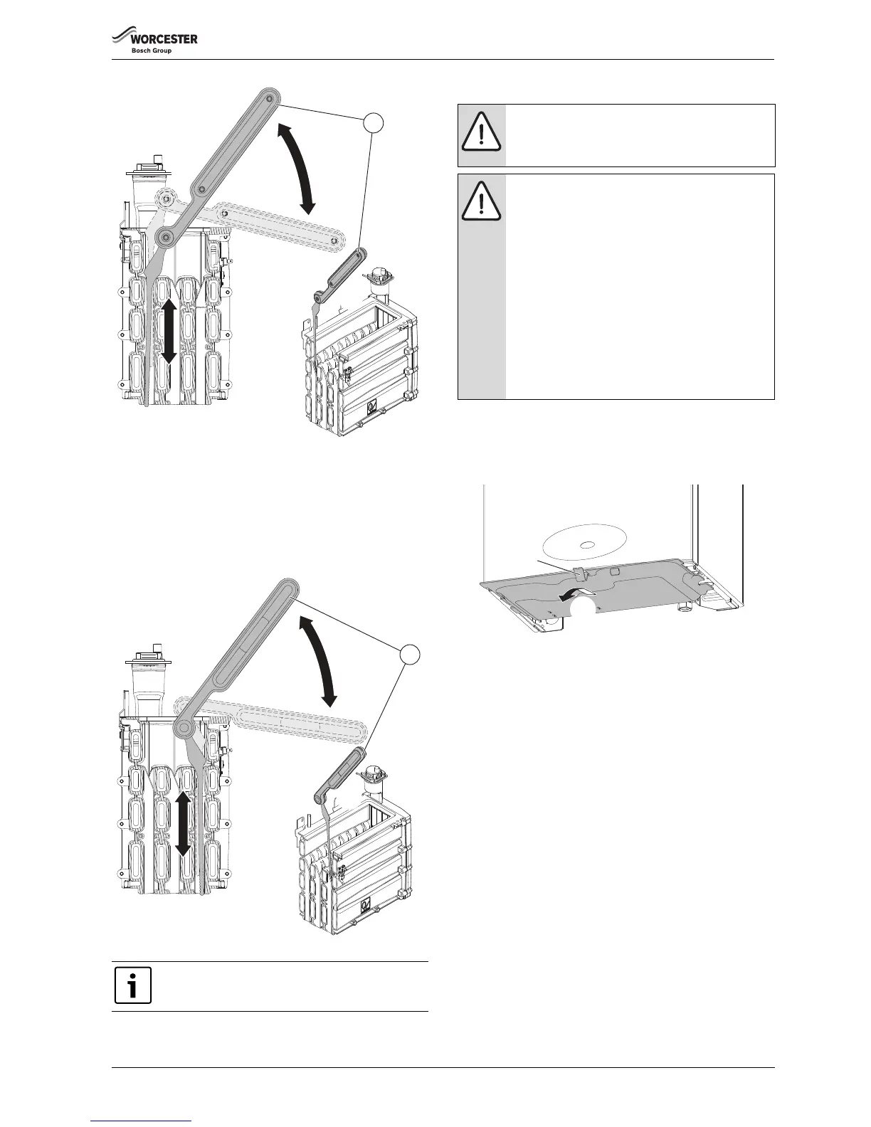
Removing the bottom panel:
1. Pull the catch down.
2. Slide the panel forward and down to remove
Fig. 75 Bottom panel
Removing the outer case:
1. Locate and remove the two screws under the front of the boiler.
2. Pull the two catches, located under the front of the boiler, down to
release the control panel
3. Pull the bottom of the control panel forward slightly and down.
4. Allow the control panel to rotate down on the hinges.
5. Remove the two screws securing the bottom of the case.
6. Release the two catches on top of the boiler.
7. Pull the case towards you and remove.
On completion of the heat exchanger cleaning and re-
assembly, perform the fan pressure test as described in
section 7.5.2
CAUTION: Mains supplies:
▶ Turn off the gas supply and isolate the mains supplies
before starting any work on the boiler and observe all
relevant safety precautions.
CAUTION: Component replacement:
▶ Replace the burner housing gasket and the Flueway
sump seal when re-assembling the heat exchanger.
Do not reassembly the heat exchanger and Flueway
until new gaskets and seals are available.
▶ After replacement of a gas related component, where
a gasket or seal has been disturbed or replaced, check
for gas tightness using a gas sniffer/analyser.
▶ On re-assembly check all affected seals for cracks,
hardness and deterioration.
If damaged or in any doubt the seal must be replaced.
▶Also after re-assembly, carry out the following
checks:
Fan pressure in section 7.5,
Flue gas analysis in section 7.6.