SERVICE AND SPARES
Greenstar Si Compact
ErP
- 6 720 813 278 (2015/07) 47
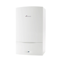
7.8.5 MAXIMUM SAFETY SENSOR (NTC)
▶ Disconnect the lead to the Maximum safety sensor.
1. Remove the screw securing the sensor.
2. Remove the sensor from the heat exchanger.
▶ When replacing the sensor, ensure that the assembly is properly
located on the orientation pin.
Fig. 80 Max safety sensor
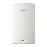
7.8.6 FLUE OVERHEAT THERMOSTAT
▶ Disconnect the lead to the flue overheat thermostat.
▶ Using a small screwdriver, gently prise the thermostat from the
housing taking care not to damage the housing or grommet.
Fig. 81 Flue overheat thermostat
▶ To replace, push the thermostat and new grommet gently back into
the opening until contact with the locating ridge is felt.
▶ The Flueway will have to be removed if the thermostat falls into the
housing, refer to section 7.8.10.
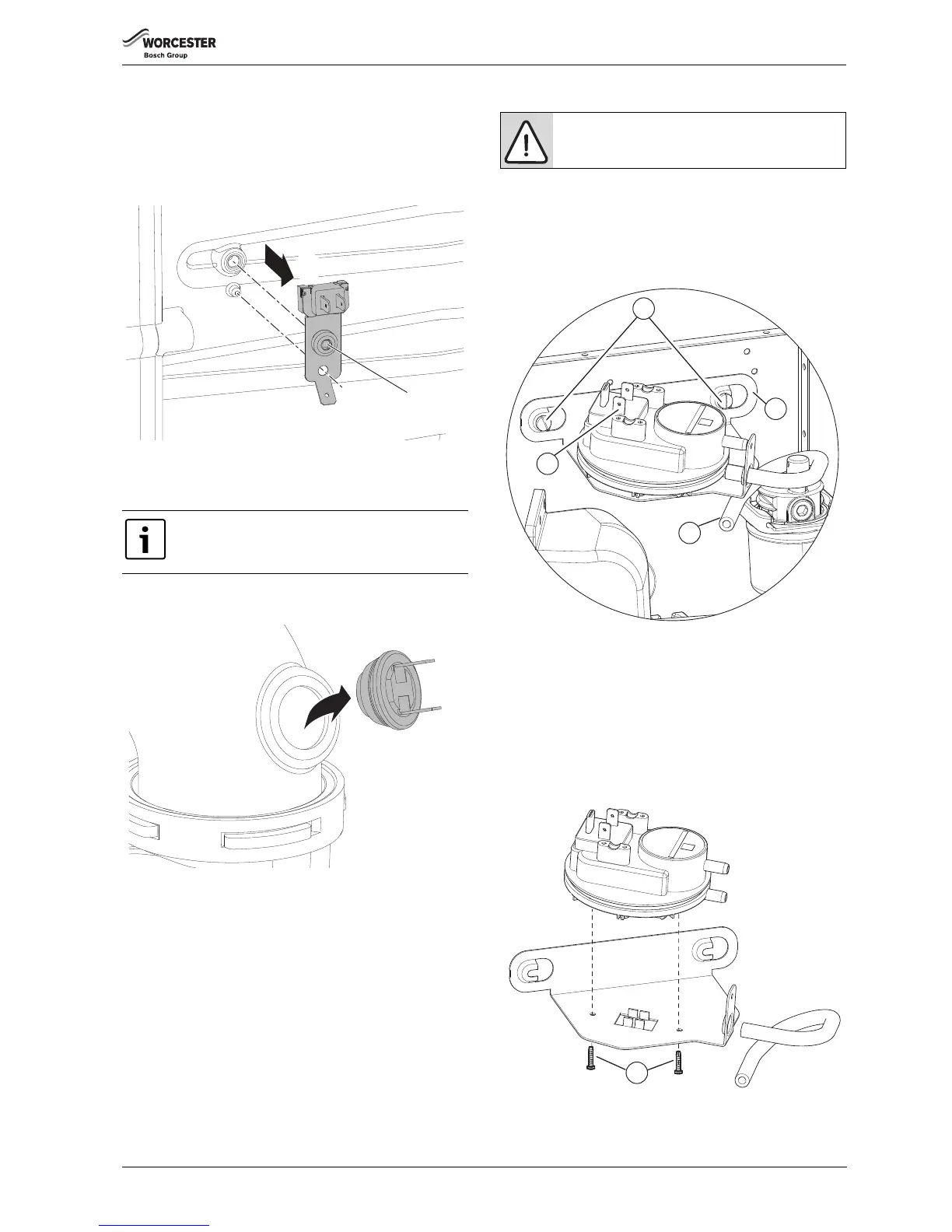
7.8.7 AIR PRESSURE SWITCH
To remove the Air pressure switch assembly:
▶ Slacken the two screws [1] but do not remove
▶ Remove the connector from the terminals [2]
▶ Disconnect the tube from the flue pipe
▶ Slide the assemble to left to release the retaining bracket
▶ Remove the assembly
Fig. 82
To remove and replace the Air pressure switch:
▶ Remove the two screws [5] retaining the switch to the bracket [4].
▶ Disconnect the tube [3] from the switch.
▶ Fit the new switch to the bracket and secure with the two screws [5].
▶ Re-connect the tube [3] to the switch, ensuring routing is looped as in
figure 82.
▶ Re-connect the connectors to the terminals [2].
▶ Align the Air pressure switch bracket [4] over the two screws [1] and
slide the assembly to the right, tighten the screws to secure.
Fig. 83
Take care not to damage the housing when removing the
thermostat.