FAULT FINDING AND DIAGNOSIS
Greenstar Si Compact
ErP
- 6 720 813 278 (2015/07)66
8.5.3 MENU 1 - SYSTEM PARAMETERS
Not applicable for Greenstar Si Compact
ErP
.
Initially Menu 1 will be displayed, but will contain no options.
8.5.4 MENU 2 - BOILER PARAMETERS
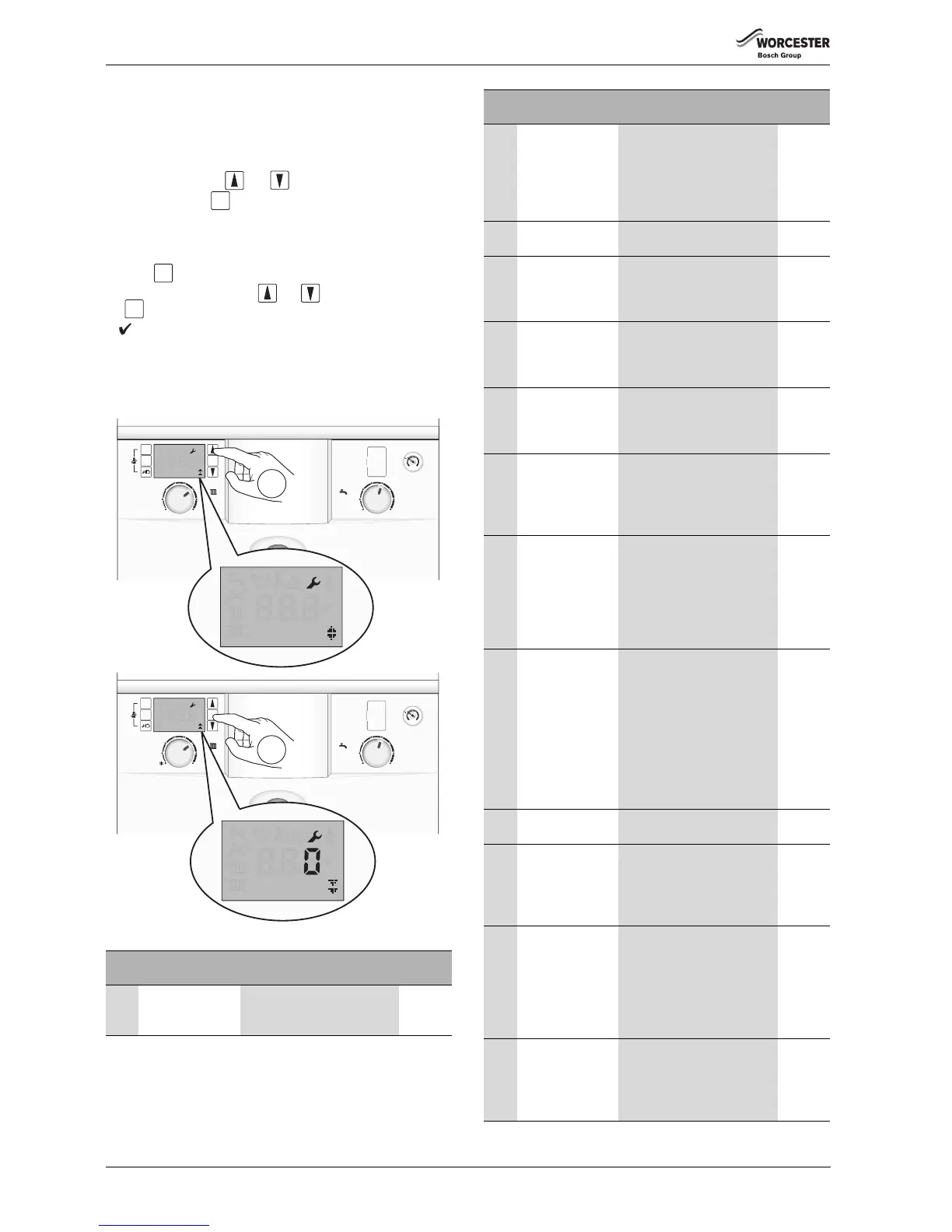
1. Select Menu 2 via the and scroll buttons.
2. Press and hold the button for one second to enter Menu 2.
This menu lists the boiler parameters, which can be adjusted in this
menu.
To modify setting, select the desired menu option (refer to table 29) and
press the button, the option will flash.
Adjust the parameter using the and arrow buttons and press
the button to confirm.
A will display for three seconds to confirm the
update of the new value.
If the setting is confirmed please record the saved value in the empty box
next to the relevant setting in Table 29.
The same process is used for adjusting all Menus 1, 2, 3 and Test.
Fig. 126 Menu 2 selection
Para
No.
Parameter Description Updated
value
2.1A Maximum power
CH
Range rate the CH of the boiler.
Adjustment in kW.
The maximum is 24kW.
Table 29 Menu 2 parameters
ok
2.1C Pump head
selection
Select the right pump map
(load and modulation
percentage) to suit the
property.
0 = Variable speed setting
1 to 4 option pump maps
2.1E Pump energy
saving mode
4 = mode ON,
5 = mode OFF
2.1H Minimum pump
speed (pump
speed at maximum
CH burner load)
This parameter is only visible
when 2.1C is set to 0. Then the
min.pump speed can be set.
2.1J Maximum pump
speed (pump
speed at maximum
burner load)
This parameter is only visible
when 2.1C is set to 0. Then the
max.pump speed can be set.
2.2C Air purge mode This feature can be selected to
purge the system and boiler of
air.
0 = off, 1 = auto, 2 = on
2.3B Anti fast cycle time
for CH
This sets the amount of time
between stop and starts of the
main heat exchanger. The
default is 5 minutes, the range
is 3 to 45 minutes.
2.3C Anti fast cycle flow
temperature
hysteresis
(negative tolerance
only)
This sets the temperature drop
before the burner re-starts, 6°K
is the default. This is used in
conjunction with the “Anti fast
cycle time”
The range is from 2 to 15°K in
1°K steps.
2.3F CH delay after DHW
demand
The default time is 1 minute
and can be adjusted to be
between 0 and 30 minutes.
This feature helps to keep the
DHW heat exchanger hot if
frequent demands are made.
The boiler will not burn extra
gas.
CH will not be heated during
this set time period.
2.5F Service reminder
time
Between 1 and 72 months can
be set
2.7A Operation/fault
indicator (blue
light) activation
0 = The blue light will only
operate as a flashing fault alert.
1 = The blue light will operate
as a boiler operation and fault
alert. This is set to 1 by default.
2.9E Turbine signal
delay
Delay time set to ignore a
temporary DHW demand.
Maximum delay is three
seconds which can be set in
¼ second increments,
e.g. 0.5 seconds is displayed as
2 or 1 second as 4.
2.9F Pump post purge
time for CH
The default pump overrun time
is 3 minutes. This can set
between 3 and 30 minutes. The
actual time will be affected by
the Pump Energy Saving mode.
Para
No.
Parameter Description Updated
value
Table 29 Menu 2 parameters