SERVICE AND SPARES
Greenstar Si Compact
ErP
- 6 720 813 278 (2015/07)52
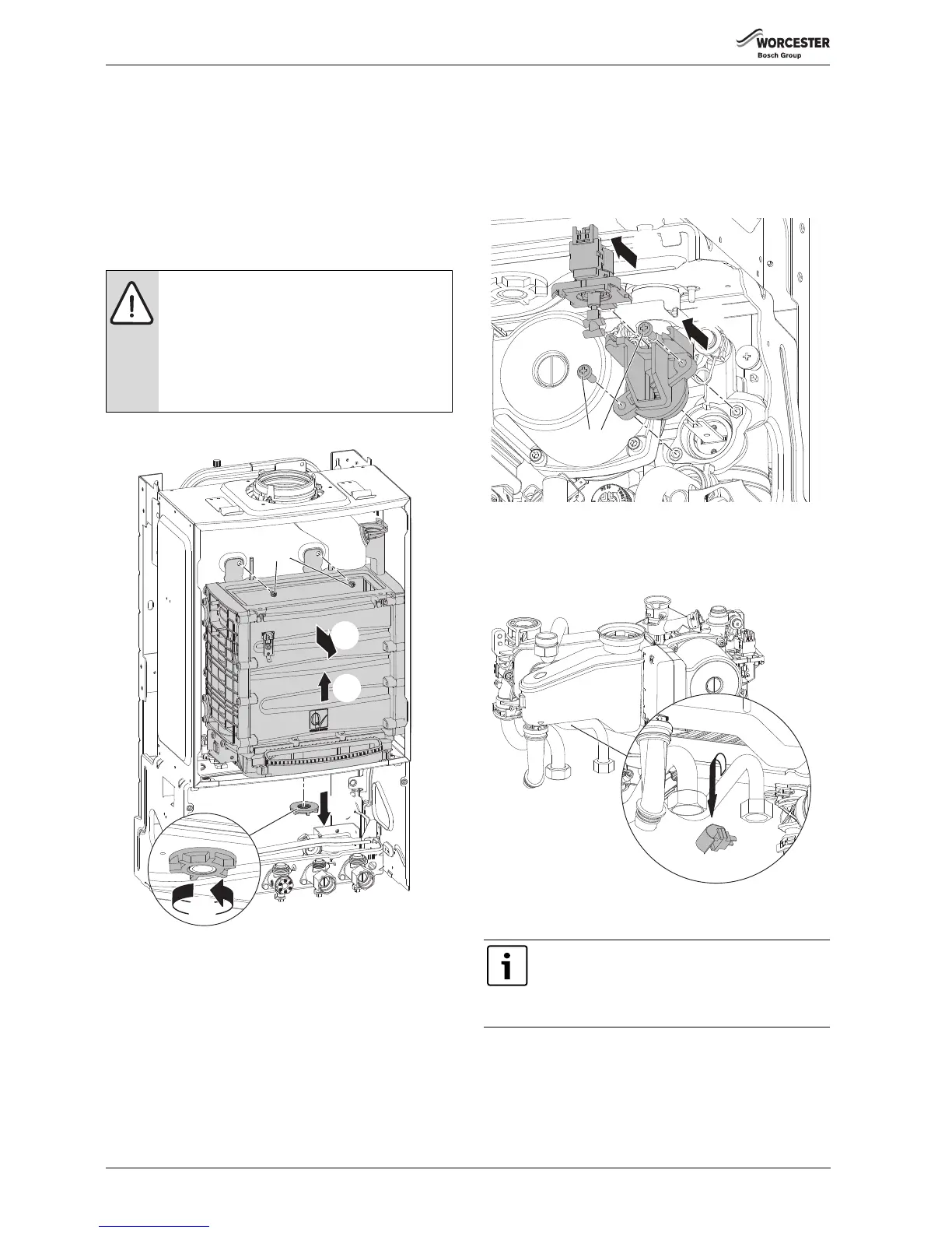
HEAT EXCHANGER REMOVAL
▶ Ensure any electrical wires or connectors are removed.
▶ Remove the Auto air vent (refer to section 7.8.8) to ease removal of
the heat exchanger
1. Unscrew the heat exchanger retaining nut.
2. Remove the heat exchanger retaining nut.
3. Remove the two screws securing the heat exchanger to the air box.
4. Lift the heat exchanger until the lower connection clears the hole in
the air box.
5. Pull the heat exchanger towards you to remove.
▶ Re-assemble in the reverse order.
Fig. 100 Heat exchanger removal
7.8.16 DIVERTER VALVE MOTOR AND DIVERTER VALVE REMOVAL
▶ Disconnect the lead from the diverter valve motor.
1. Pull the diverter valve motor from the housing.
2. Undo and remove the two screws from the diverter valve motor
housing.
3. Pull the diverter valve motor housing from the diverter valve
assembly.
Fig. 101 Diverter valve
7.8.17 DHW TEMPERATURE SENSOR (NTC)
▶ Disconnect the electrical connector from the sensor.
▶ Unclip the sensor from the pipe.
Fig. 102 DHW temperature sensor
7.8.18 PUMP HEAD
1. Disconnect the main electrical connector from the bottom of the
pump.
2. Remove the four screws securing the pump head.
3. Pull the pump free from the housing.
▶ Ensure that the pump body is completely dry before fitting the new
pump head, failure to do so may result in damage to the pump.
CAUTION: Component replacement:
▶ After replacement of a gas related component, where
a gasket or seal has been disturbed or replaced, check
for gas tightness using a gas sniffer/analyser.
▶Also after re-assembly, carry out the following
checks:
Fan pressure in section 7.5,
Flue gas analysis in section 7.6.