FAULT FINDING AND DIAGNOSIS
Greenstar Si Compact
ErP
- 6 720 813 278 (2015/07) 65
8.5.2 SELECTING SERVICE MENUS
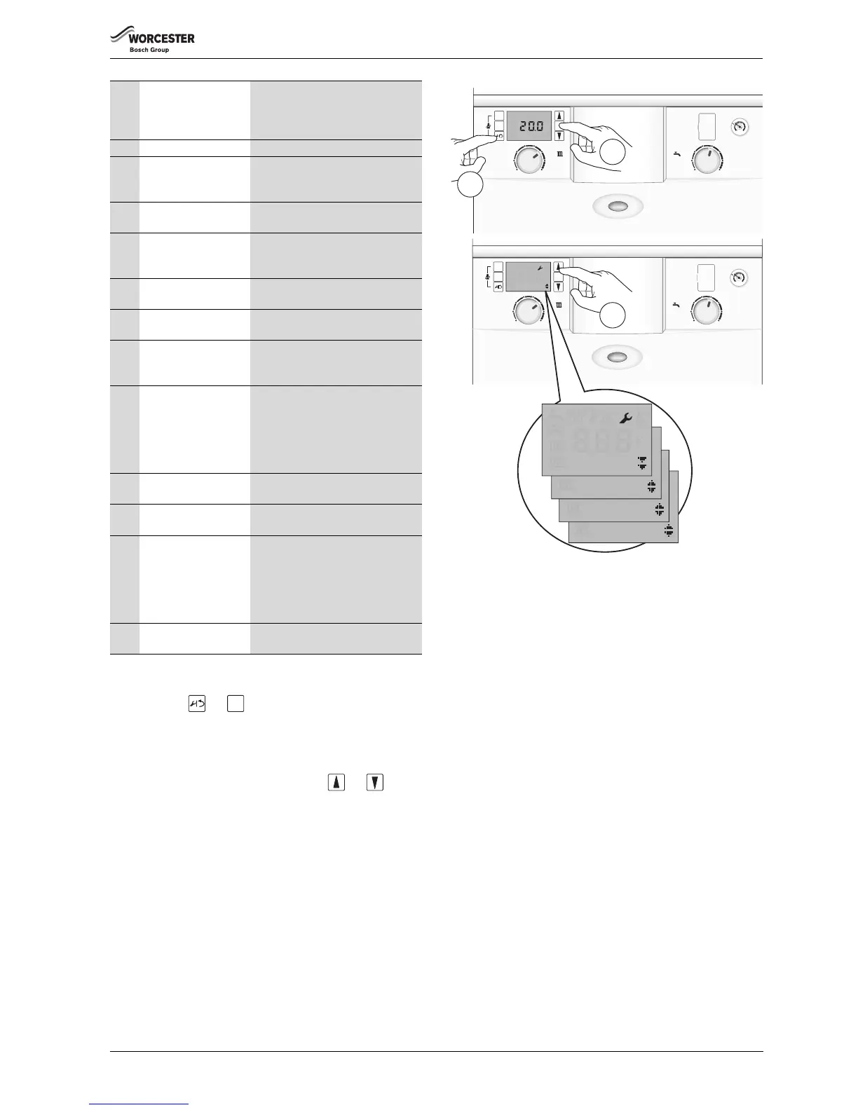
1. Press and hold and buttons together for one second, the
display will show Menu 1.
Double up or down arrows indicate that the menu can only be scrolled up
or down, an up and down arrow combination indicates position in the
menu where options can be scrolled either up or down.
2. Scroll up and down through the menus with the and buttons
on the right hand side of display.
Fig. 125 Service menu selection
i10 Maximum temperature This is the current temperature from
the “Maximum safety sensor”. This
sensor is mounted on the front of the
heat exchanger.
i11 DHW flow temperature The current DHW flow temperature.
i12 DHW temperature
setpoint
This is the temperature selected via
the Hot Water control knob on the
fascia.
i14 Return temperature The current temperature returned to
the main heat exchanger.
i15 Outdoor temperature Optional outdoor temperature sensor
needs to be connected for this menu
to be activated.
i16 Pump modulation The current pump modulation is
displayed as a percentage.
i17 Burner modulation The current burner modulation is
displayed as a percentage.
i18 Fan speed The current fan speed is displayed in
Hertz. The value is up-dated in real
time.
i19 Time inputs This indicates the status of the
optional fascia mounted controls:
0 = CH off, DHW off
1 = CH off, DHW on
2 = CH on, DHW off
3 = CH on, DHW on
i20 Software version Firmware version of the main control
board.
i21 Software version Firmware version of the fascia control
display board
i22 Heat Control Module
(HCM) number.
The last three digits of the HCM are
displayed:
586 = 25kW Combi N.G.
587 = 25kW Combi L.P.G.
588 = 30kW Combi N.G.
589 = 30kW Combi L.P.G.
i23 Heat Control Module
(HCM) version number.
For example “4”
Table 28 Information menu listing
ok