SERVICE AND SPARES
Greenstar Si Compact
ErP
- 6 720 813 278 (2015/07) 57
▶ Lower the control panel into the service position.
▶ Isolate the boiler from the heating system using the service valves.
▶ Drain the boiler.
▶ At the pump manifold, release the clip and disconnect the expansion
vessel.
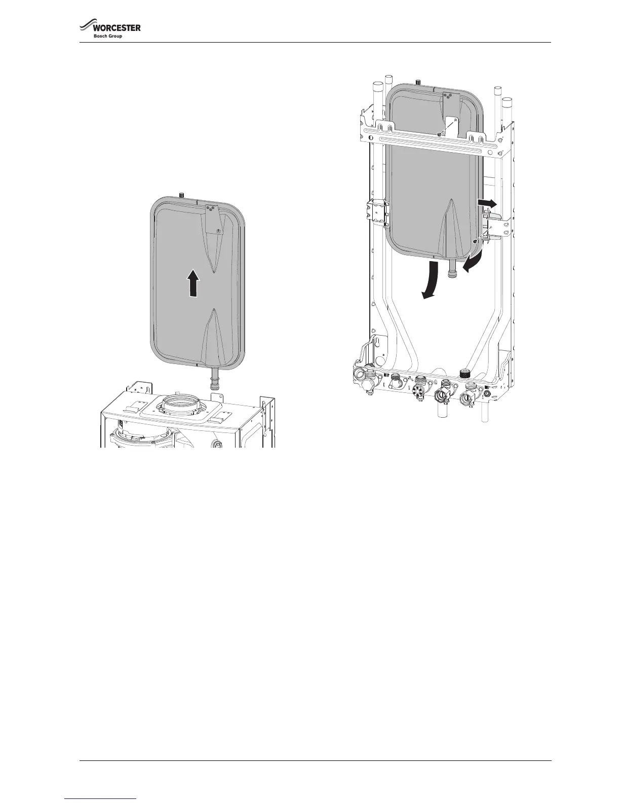
▶ Pull the vessel up and out over the flue system or to one side if a
vertical flue is fitted.
▶ Fit a new “O” ring to the replacement vessel and smear with silicone
grease.
▶ Reassemble the expansion vessel into the wall frame and slide down
the runners until the end pipe is reconnected into the pump manifold.
▶ Secure the pipe with spring clip
Fig. 119
EXPANSION VESSEL REPLACEMENT (BOILER REMOVED)
▶ Isolate the power from the boiler.
▶ Isolate the heating systems and gas connection using the service
valves.
▶ Drain the boiler.
▶ Disconnect the electrical supply and any external controls.
▶ Disconnect the flue from the boiler.
▶ Undo the connections to the boiler at the service valves.
▶ Lower the control panel into the service position.
▶ At the pump manifold, release the clip and disconnect the expansion
vessel.
▶ Lift the expansion vessel up to clear the pump manifold connection.
▶ Secure the expansion vessel to the wall frame by the bracket at the
top.
▶ Undo the two screws at the bottom of the case.
▶ Release the clips at the top of the case and slide the case towards you
to remove.
▶ Disconnect the pipes and siphon discharge hose from the plumbing
manifold.
▶ Disconnect the PRV.
▶ Lift the boiler off the wall frame.
1. Remove the screw retaining the expansion vessel to the wall frame.
2. Remove the screw securing the right hand expansion vessel mount.
3. Slide the mount to the right to release the expansion vessel.
4. Pull the expansion vessel towards you.
5. Pull the expansion vessel down to remove.
Fig. 120 Removing the expansion vessel
▶ Replace the expansion vessel in the reverse order.
▶ Follow the procedures in this manual for commissioning this product.