Pre-Installation
Greenstar Danesmoor Utility
ErP
and Utility System
ErP
- 6 720 813 286 (2014/09) 13
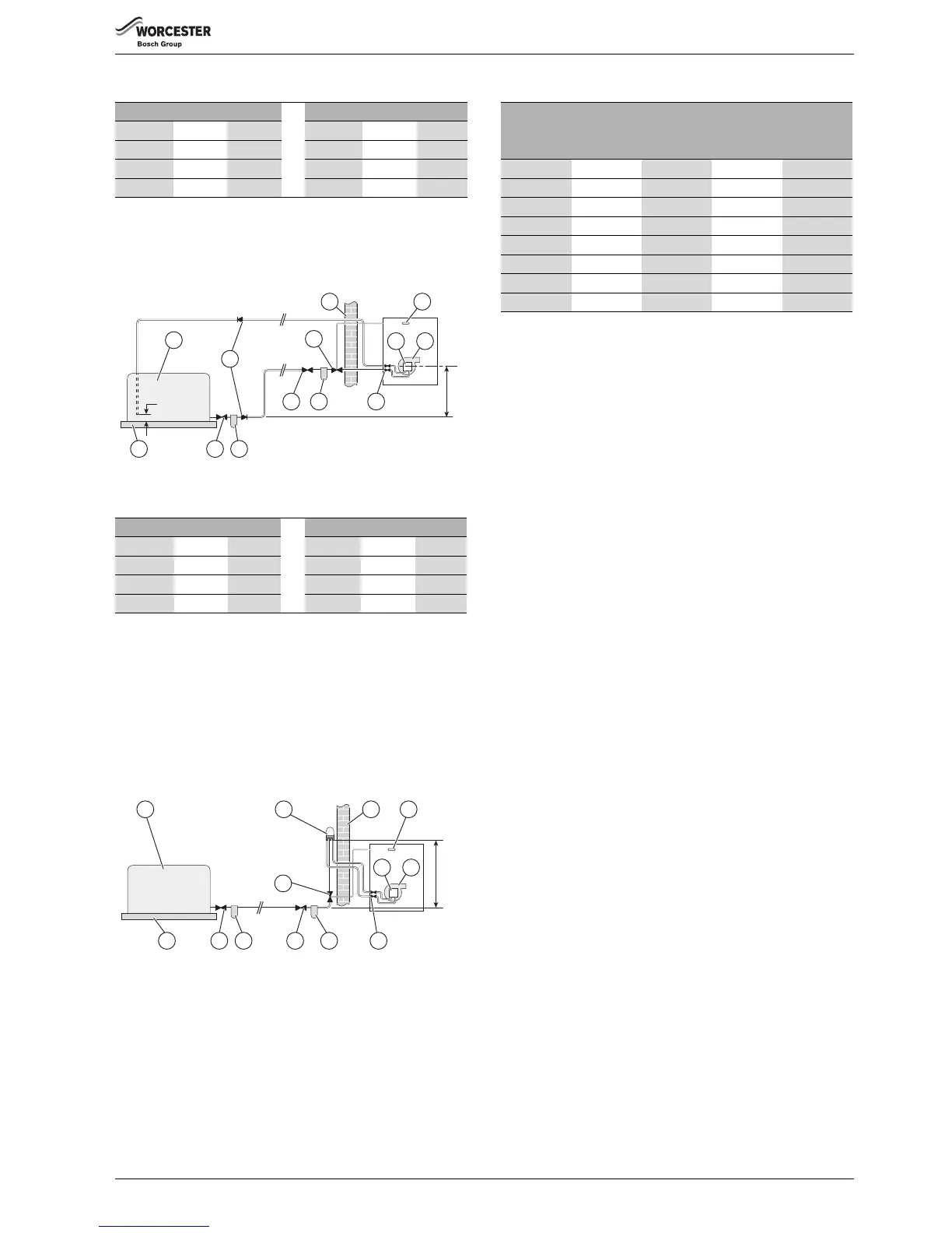
Maximum pipe run for single pipe gravity fed system
4.3.2 Double pipe sub-gravity feed system:
Maximum suction height 3.5 metres. Non-return valves must be fitted to
the inlet and return oil line between the oil pump [9] and oil storage tank
[1].
Fig. 8 Double pipe feed
Maximum pipe run for double pipe sub-gravity fed system
4.3.3 Single pipe suction lift with de-aerator:
Maximum suction height 3.5 metres. The oil tank [1] must be positioned
below the oil pump [9]. Create an inlet and return loop between the de-
aerator [12] and oil pump [9].
A non-return valve must be incorporated within the de-aerator or fitted
to the oil line between the oil storage tank [1] and the de-aerator [12].
A top feed oil tank fitted with a de-aerator using an internal non-return
valve should have any non-return valves fitted in the base of the tank to
the suction line removed to assist purging air from the oil line.
Fig. 9 De-aerator feed
Maximum pipe run for single pipe suction lift with de-aerator
[NOTE:] The table and illustration above is a guide only and does not in
any way override the de-aerator manufacturer’s instructions
4.3.4 Pipework
▶ Refer to the oil supply sections Single pipe gravity feed
system: 4.3.1, Double pipe sub-gravity feed system: 4.3.2 & Single
pipe suction lift with de-aerator: 4.3.3 for oil supply pipework
configurations.
Oil supply pipework considerations:
• Lay the oil supply pipe as straight and level as possible to avoid air
pockets and unnecessary friction losses.
– Route away from the boiler access door or other hot surfaces.
• Install a manual isolating valve to the oil supply pipe, as close to the
oil storage tank as possible.
• Fit an oil strainer and water separator to the oil supply pipe, near the
oil storage tank.
– Fit an additional oil filter (70 μm max filtration size) close to the
boiler, but not inside the boiler casing.
• Fit a fire valve in accordance with BS 5410.
– The fire valve should be fitted externally to the building with the
fire valve sensor located within the appliance case.
– A fire valve with a shut off temperature of 85°C or higher must be
fitted to avoid the possibility of nuisance shut offs.
– A capillary type valve provides a neat and simple installation.
Alternatively, a fusible link or electrical system may be used.
• Under no circumstances should a combination isolating/fire valve be
used as the sole fire protection device.
4.3.5 Boiler isolation valve
▶ Use copper pipe of the correct diameter according to the information
shown in oil supply sections 4.3.1, 4.3.2 & 4.3.3.
– If using soft copper pipe (R220) with a compression fitting, an
insert must be used to prevent the pipe from collapsing or
distorting when the fitting is tightened.
▶ Slide nut [1] and olive [5] onto the oil supply pipe [4].
▶ Slide insert [3] into the pipe.
Head (m) 10mmØ 12mmØ Head (m) 10mmØ 12mmØ
0.5 12 30 2.5 62 100
1.0 25 69 3.0 74 100
1.5 37 91 3.5 87 100
2.0 49 100 4.0 99 100
Head (m) 10mmØ 12mmØ Head (m) 10mmØ 12mmØ
050100 2.0 26 66
0.5 44 100 2.5 20 50
1.0 38 95 3.0 14 37
1.5 32 80 3.5 8 22
 Loading...