Installation
Greenstar Danesmoor Utility
ErP
and Utility System
ErP
- 6 720 813 286 (2014/09) 27
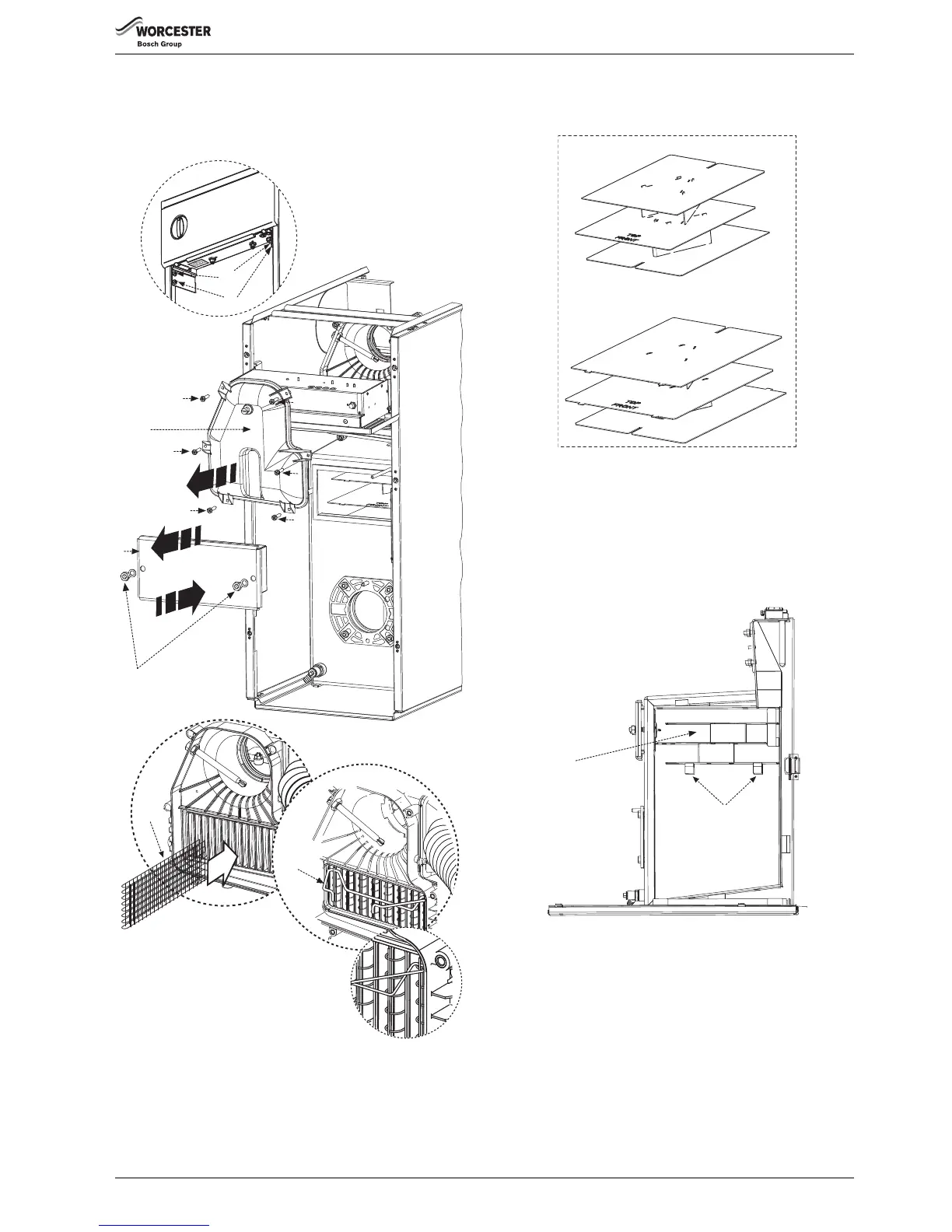
5.5 Combustion chamber (18/25 Regular shown)
1. Remove the control box securing screws (A, bottom screw both
sides) and loosen the pivot screws (B, top screw both sides).
2. Pivot down control box.
Fig. 43 Combustion chamber
3. Release retaining nuts and washers (C).
Remove baffle/combustion chamber access door (D).
4. Ensure one piece baffle set (E) is in the right location (F), correctly
resting on the baffle rests (G) on either side of the combustion
chamber and pushed securely into place.
Fig. 44 Baffle arrangement
5. Secure baffle/combustion chamber access door (D) with nuts and
washers (C). Tighten until door is firmly secured. Do not overtighten
the nuts.
6. Unscrew screws (H) and remove flue manifold access cover (I).
7. Check that all the baffles (J) and baffle retainer (K) are correctly
fitted to the secondary heat exchanger.
Hook the retainer (K) over the end two baffles.
Fig. 45
2.
3.
6.
H
7.
J
H
H
D
I
H
H
H
C
5.
1.
A
B
K
6720809436-25.1Wo
 Loading...