Installation
Greenstar Danesmoor Utility
ErP
and Utility System
ErP
- 6 720 813 286 (2014/09)28
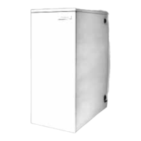
5.6 Pipework connections
Fig. 46 Pipework connections
[A] Return connection 22mm Ø copper (28mm Ø on 25/32 models)
[B] Flow & optional combined feed and vent 1” BSP
[B1] Flow connection 22mm copper (28mm on 25/32 models)
[C] Pressure relief valve
[D] Flue manifold condensate outlet
[E] Condensate trap - supplied
[F] Condensate outlet & flexible push fit connection (21.5mmØ)
[G] Fixing point for optional oil return pipe
[H] Oil isolating valve (10mmØ )
[J] Flexible oil hose and routing
[K] Primary Drain (hose connection)
[L] Pump circuit drain point
[M] Pressure gauge connection
[N] Expansion vessel connection
Water connections
▶ Remove the transit bungs from the pipework connections on e boiler.
▶ Ensure all of the pipework is clean.
▶ Align the water pipework and connect. The 12/18 and 18/25 return
pipe only, may be cut to simplify pipe routing externally to the boiler.
▶ Check that all the unused sockets have been capped.
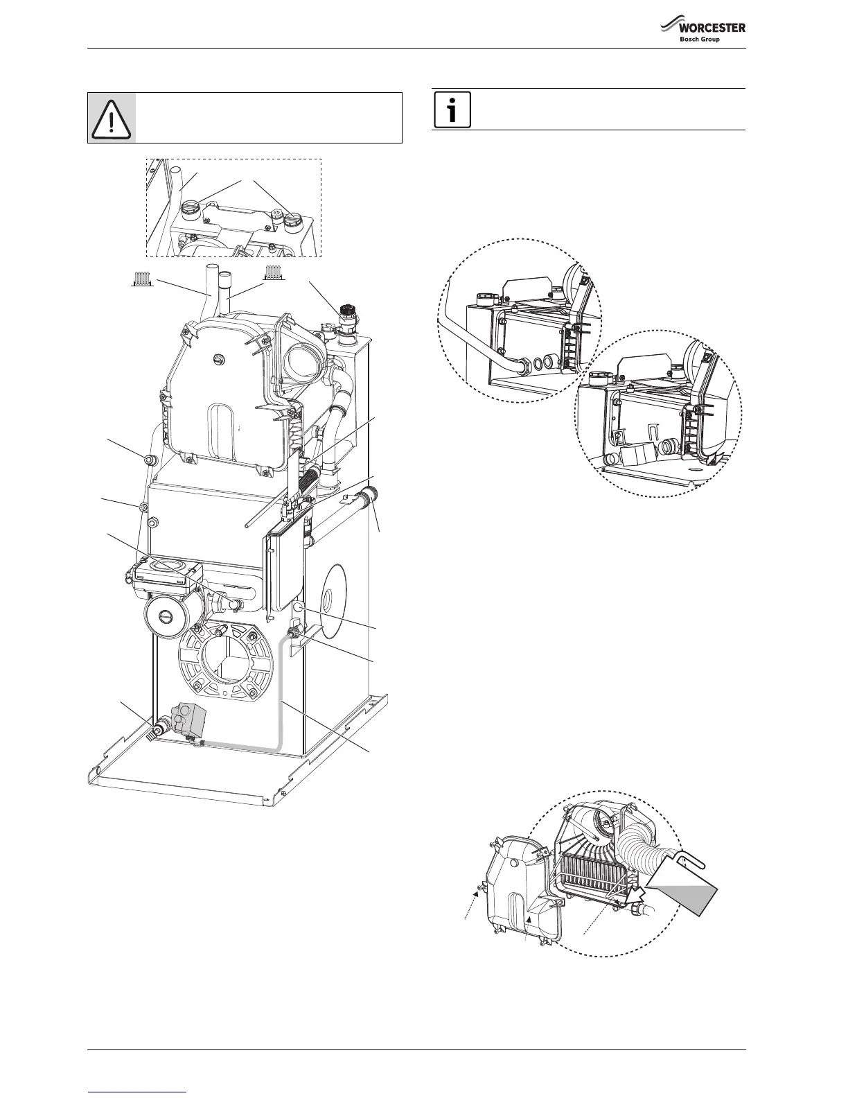
Return pipe connection
Fig. 47 Return pipes
Oil supply connections
▶ Refer to figure 46 and ensure that the isolating valve (H) is closed and
route the oil supply pipe along the right side of the boiler and connect
to the isolating valve (H).
Condensate connection
▶ Connect the 21.5mm polypropylene pipe (not supplied) to the
condensate waste pipe flexible push fit connector (F) and terminate
to waste. Do not use any solvents, adhesives or lubricants when
pushing the pipe into the flexible push fit connector (F).
▶ Ensure that the condensate pipe runs away from the boiler at a
constant fall of 52mm (minimum) for every metre.
▶ Carefully pour 500ml of water into the condensate collection (P) to
fill condensate trap.
▶ Check the water is running away and the condensate pipework joints
are water tight.
▶ Check the flue manifold seal is undamaged and seated correctly.
▶ Refit flue manifold access cover (R) and secure with screws (S).
Fig. 48 Condensate
[P] Condensate collection sump
[R] Manifold access cover
[S] Screws x 6
CAUTION: MAINS SUPPLIES
▶ Isolate the oil & water mains supply before starting
any work and follow all relevant safety precautions.
 Loading...