Installation
Greenstar Danesmoor Utility
ErP
and Utility System
ErP
- 6 720 813 286 (2014/09) 25
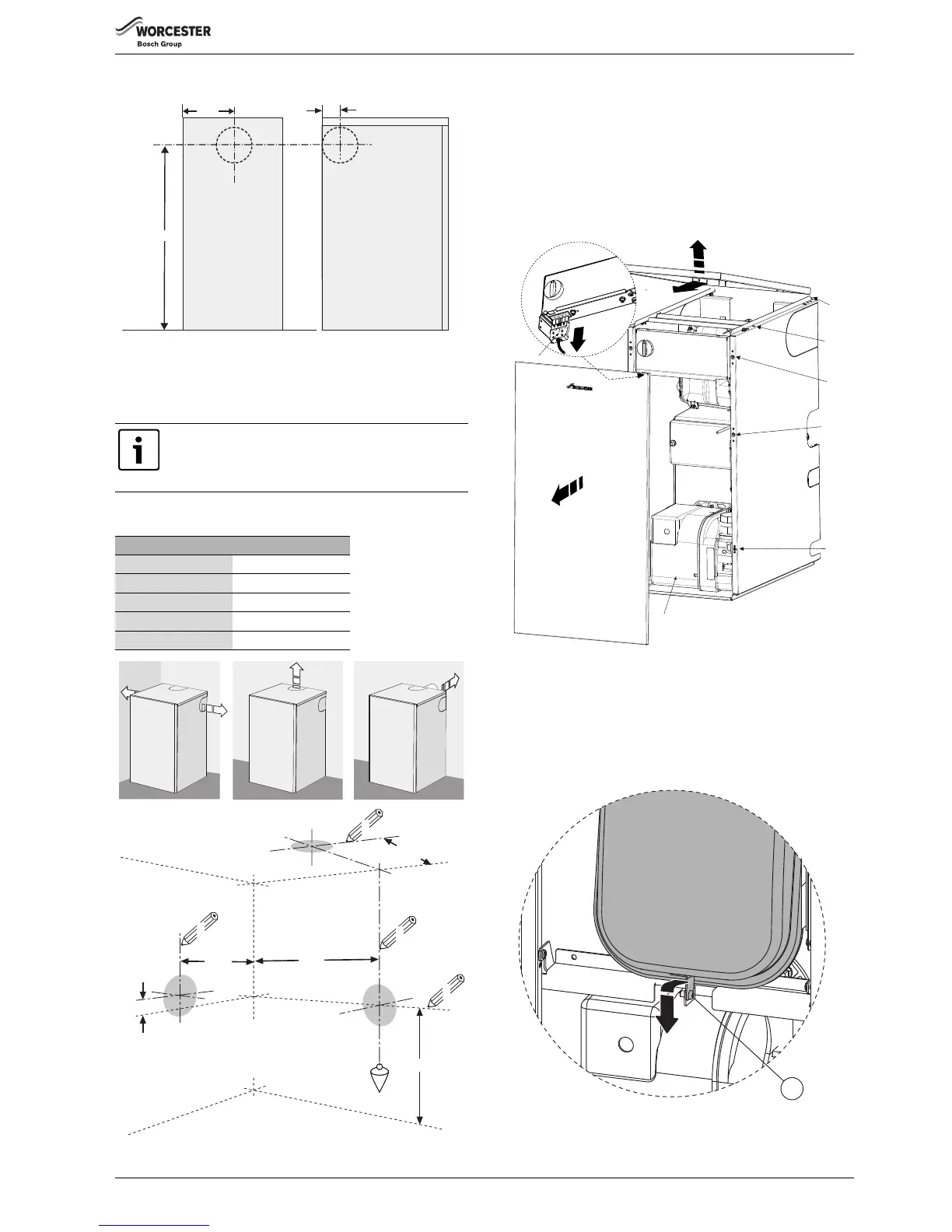
Flue centres
Fig. 33 Flue centres
Flue opening
▶ Follow figure 34 to mark the centre of the flue (1, & 2) for rear
opening, (2 & 3) for side opening or (1 & 4) for top opening.
▶ Make an opening (F, G or H) using a core drill or similar at a size
relative to the wall thickness as shown below:
Fig. 34 Flue opening
5.3 Boiler installation
1. Lift the front of the top panel (A) upwards to disengage the ball stud
connections (B) and pull forwards to release from the brackets (C) at
the back to remove. Pull front panel (D) forward from the bottom and
near the top disengaging the ball studs from their connections (E)
and lift off the ledge (F) that runs along the bottom of the fascia to
remove.
2. Unplug burner lead (G) from control box.
Fig. 35 Boiler installation
Utility system only:
▶ In the case of the Utility system boiler, remove the retaining screw
[1] at the base of the expansion vessel.
▶ Pull the expansion vessel forward slightly and down to remove.
Place to expansion vessel outside of the boiler, taking care not to kink
or stretch the flexible hose.
Fig. 36
All horizontal flue sections must rise away from the boiler
by 52mm per metre to ensure that condensate flows
back into the boiler for safe discharge via the condensate
waste pipe.
125mm Ø flue:
Wall thickness mm Flue hole size Ø mm
150 - 240 155
240 - 330 160
330 - 420 165
420 - 500 170
 Loading...