Appliance information
Greenstar Danesmoor Utility
ErP
and Utility System
ErP
- 6 720 813 286 (2014/09) 9
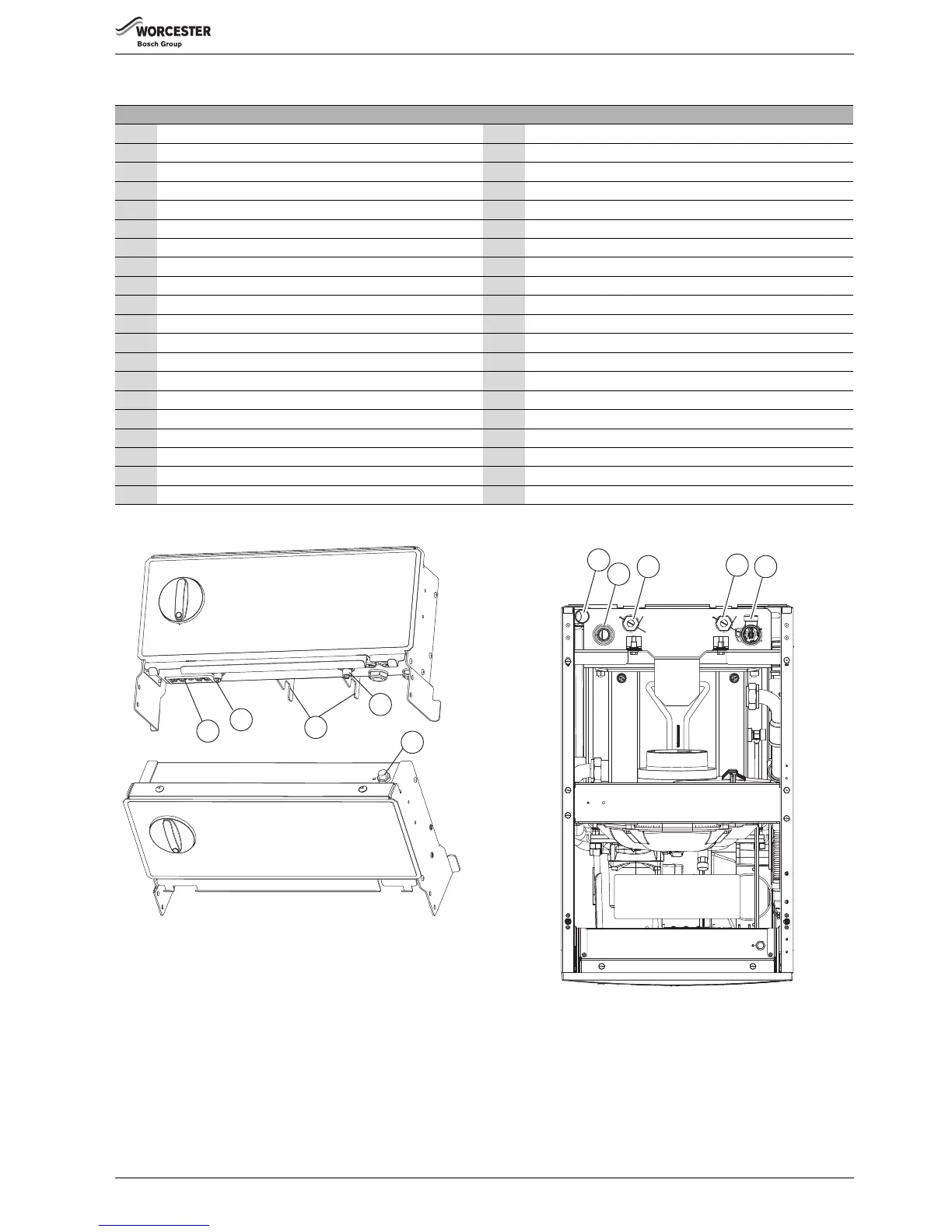
Fig. 1 System appliance shown
Fig. 2 Control panel thermostat detail
Fig. 3 Top view connections
Figure 1 does not include the top, front, left, and right hand side panel
1 Return connection 21 Oil pump (behind plastic cover)
2 Flow connection 22 Burner control box (behind plastic cover)
3 Pressure relief valve 23 Riello RDB burner
4 Air inlet casing 24 Lock out reset button (on the front of the burner control box)
5 Secondary heat exchanger flow pipe 25 Expansion vessel
6 Secondary heat exchanger baffles 26 Control box assembly
7 Baffle retaining clip 27 Temperature control knob
8 Secondary Heat exchange drain point 28 Flue manifold access cover
9 Condensate discharge 29 Flue gas sampling point
10 Condensate trap 30 Combustion chamber access door (primary baffle inside)
11 Optional oil return position 31 System pressure gauge
12 Oil isolating valve 32 Flue overheat thermostat phial
13 Primary heat exchanger 33 Secondary heat exchanger
14 Pump drain point 34 Burner lead connector socket
15 Burner mount plate 35 Flue thermostat reset
16 Base plate and oil drip tray 36 Expansion vessel retaining bracket
17 Circulating three speed pump 37 High limit thermostat reset
18 Primary heat exchanger drain point 38 Auto reset thermostat
19 Burner air intake 39 Control & manual reset overheat thermostat phial
20 Burner motor (behind plastic cover) 40 Auto-reset high-limit thermostat phial
Table 3 Appliance component details
34
35
36
37
38
6720809436-04.1Wo
 Loading...