OPEN FLUE MODEL (CF/LLD)
This includes conventional flue and standard low level and high
level horizontal discharge kits.
6.1 In order to ensure clean and efficient combustion, an
adequate supply of air must be delivered to the combustion
chamber. To provide sufficient air, a suitable inlet should be
provided into the room or space in which the appliance is
situated, the size of which is detailed in Table 7. An air brick or
other form of continuous air supply may have to be built into
the installation in order to ensure an adequate supply of air.
6.2 If the appliance is to be installed in a confined space or
compartment, two air vents are required, one at high level and
one at low level. The minimum free area of each vent is given in
Table 8 and depends whether the air is taken from another room
or from outside the building. Where the air is taken from another
room that room must contain an air inlet as described in 6.1.
6.3 There must be sufficient clearance around the appliance to
allow proper circulation of ventilation air. The clearances
required for installation and servicing will normally be adequate
for ventilation. See Section 4.4.
ROOM SEALED BALANCED FLUE MODEL (RS)
6.4
The appliance does not require a separate vent for
combustion air.
6.5 Installation in cupboards or compartments require
permanent vents for cooling purposes, one at high level and one
at low level, either direct to outside air or to a room. Both vents
must pass to the same room or be on the same wall to the
outside wall to the outside air. The minimum air vent free area is
given in Table 9.
6.6 There must be sufficient clearance around the appliance to
allow proper circulation of ventilation air. The clearances
required for installation and servicing will normally be adequate
for ventilation. See Section 4.4.
A flue system must be provided in accordance with BS5410:
Part 1 and with the current Building Regulations.
7.1 Conventional Flue (CF). See Fig 5.
Conventional Flue Diameters: 12/14 – 100mm (4in.)
15/19 – 100mm (4in.)
20/25 – 100mm (4in.)
26/32 – 125mm (5in.)
NOTE: External flues systems must be of the insulated flue type.
The boiler is fitted with a conventional flue locating spigot.
7. Flue System6. Air Supply
11
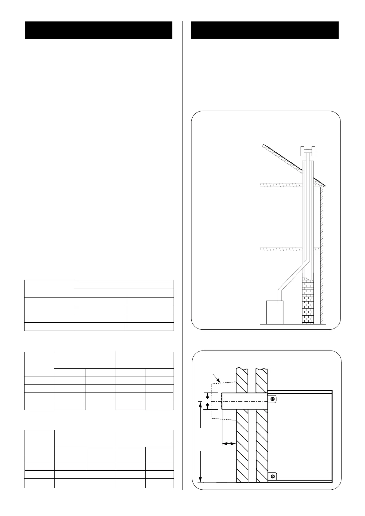
Fig. 7. Flue Installation.
Where possible take the
flue above the apex – if not
above the apex an anti
down-draught terminal is
advisable.
Brick Chimney.
Use of a flue liner
is recommended.
Use as few bends as
possible.
Use 135° Bends.
Flues must not be reduced from
the boiler take off diameter.
ALWAYS TAKE THE FLUE ABOVE THE EAVES
Fig. 8. Flue Installation (Rear Discharge).
See Fig. 10 for flue
terminating positions.
80
min.
FLUE GUARD
766 mm
140
Table 8. Minimum Air Vent Free Area for Open Flue
appliances installed in a compartment.
Appliance
Ventilation to room or
Ventilation to outside
model
internal space
High Level Low Level High Level Low Level
12/14 154cm
2
231cm
2
77cm
2
154cm
2
15/19 209cm
2
314cm
2
105cm
2
209cm
2
20/25 275cm
2
413cm
2
138cm
2
275cm
2
26/32 352cm
2
528cm
2
176cm
2
352cm
2
Table 9. Minimum Air Vent Free Area for Room Sealed
appliances installed in a compartment.
Appliance
Ventilation to room or
Ventilation to outside
model
internal space
High Level Low Level High Level Low Level
12/14 154cm
2
154cm
2
77cm
2
77cm
2
15/19 209cm
2
209cm
2
105cm
2
105cm
2
20/25 275cm
2
275cm
2
138cm
2
138cm
2
26/32 352cm
2
352cm
2
176cm
2
176cm
2
APPLIANCE
AREA OF AIR INLET
cm
2
in.
2
12/14 77 12
15/19 105 16.5
20/25 138 21.5
26/32 176 27.5
Table 7. Minimum Combustion Air Inlet Free Area for
Open Flue appliances
 Loading...


