Refer to Figs. 18, 19, 20 and 21.
13.1 The wiring between the appliance and the electrical supply
shall comply with current IEE Wiring Regulations (and any local
regulations which apply) for fixed wiring to a stationary
appliance.
NOTE: It must be possible to completely isolate the appliance.
13.2 To gain access to the mains connection point on the
control board.
1. Isolate the mains electrical supply.
2. Remove the cabinet top panel by snatching squarely upwards.
3. Release the four screws securing the cover of the electrical
control box.
13.3 Mains Supply
Mains Supply-230V~ 50 Hz.
External Fuse 5A to BS1362. Internal Fuse 3.15A (20 mm). Slow
Blow.
LIVE-Brown, NEUTRAL-Blue, EARTH-Green/Yellow
Mains Cable: 0.75mm
2
(24 x 0.20mm) to BS6500 Table 16.
The supply to the boiler must be the only electrical supply to the
system. This ensures the safety of a single fused supply.
NOTE: Under no circumstances should the timer be connected
to a separate electrical supply. Safety is assured from a single
fused supply to the boiler.
The method of connection to the appliance must allow complete
isolation of the appliance, preferably via a double pole isolator
with a contact separation of 3mm in all poles supplying the
boiler and controls only.
13. Electrical
21
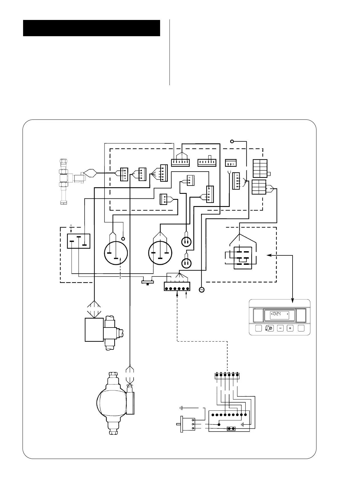
Fig. 18. Wiring Diagram.
Flow switch
Earth
Boiler
High Limit
Thermostat
Domestic Hot
Water Control
Thermostat
Manual reset
overheat thermostat
Earth
Central Heating
Control Thermostat
Optional Programmer
Mains Electrical Supply
Operating Switch
FAN MOTOR
PLUG-IN
CONNECTOR
12345
6
123 456
1
E
E
E
N
N
L
234567 89
SATRONIC CONTROL BOX
Burner Control Options
Plug-in connector
to burner control
Pump
Motorised
Diverter
Valve
COLOUR CODE
br – brown bl – blue gy – green and yellow
r – red w – white y – yellow g – grey
bk – black or – orange pk – pink
Facia Panel
POWER ON
Indicator light
LOCKOUT
Indicator light
Link
Link
Post purge
unit connection
X6
X7
X8
X13
X1
X10
X12
X11
X3
X4
X9
bl
bl
bl
gy
or
br
gy
gy
g
g
bk
gy
br
or
or
or
bl
bk
bl
br
r
pk g
gy
gy
y
gy
br
bk
r
pk
g
gy
y
bl
or
bk
g br
pk
y
r
ww
br
(1)
(1)
(1)
(3)
(C)
(C)
(3)
(C)
br
br
br
br
bl
bk
g
br
pk
y
y
y
y
y
y
pk
pk
pk pk
White
Grey
White
Brown
Brown
or
bl
w
w
w
pk
 Loading...


