17
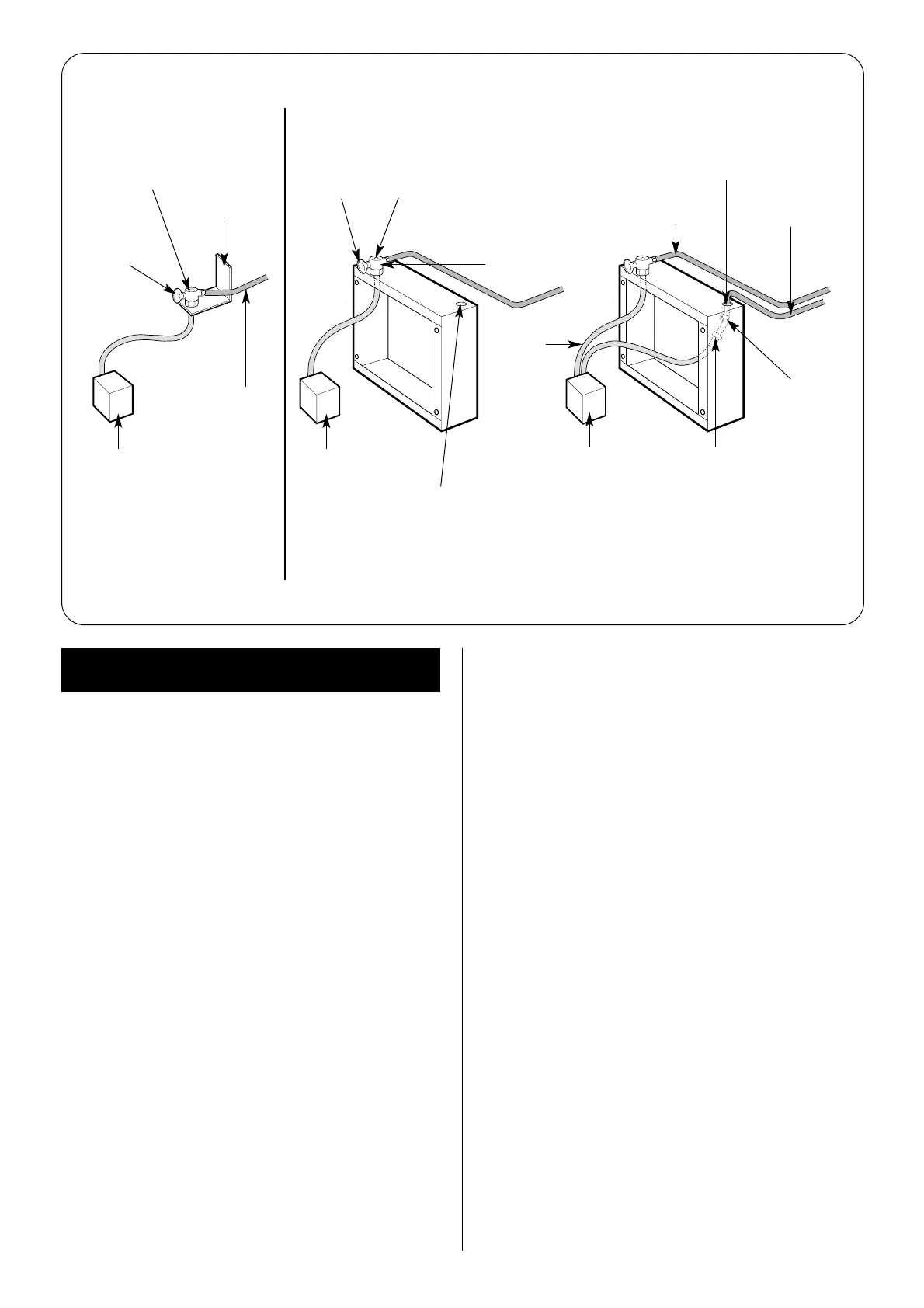
Fig. 14. Oil Pipe Installation.
(b) Single Pipe System.
RS Appliance
(a) CF Bracket.
CF Appliance
(c) Double Pipe System or
Single Pipe Suction Lift with De-aerator.
Burner
oil pump
Open
grommet
Turn fully
clockwise
to isolate
Blind
grommet
Air
bleed
Burner
oil pump
Burner
oil pump
10mm or 12mm
copper pipe
1
⁄4" BSP female x
10/12mm
compression coupling
(not supplied)
10mm
copper pipe
10mm
copper pipe
Retaining
clip
Isolating
valve
Isolating
valve
Pipe support
bracket
Turn fully
clockwise
to isolate
Flexible
oil hose
The heating and hot water system must be provided in accor-
dance with the current Building Regulations.
9.1 The appliance incorporates a circulating pump. No other
pump is required. The appliance will operate satisfactorily on a
two-pipe small bore or micro bore system using
thermostatically controlled radiator valves.
9.2 The appliance incorporates a three-port, two-way diverter
valve which diverts the boiler output to the Heatslave tank in
response to a demand from the Domestic Hot Water Control
Thermostat or the flow switch. The valve is powered open in
response to a demand from the Central Heating Control
Thermostat or a room thermostat, and the boiler output is
diverted to the heating circuit.
If there is a demand from both the Heatslave tank and the
central heating, the valve will give priority to the Heatslave tank.
The central heating will therefore remain switched off for a short
period of time. This delay will vary depending on the appliance
output and the quantity of energy required to satisfy the
domestic hot water demand.
The Heatslave tank priority can be temporarily overridden to
regain the central heating output by turning the Domestic Hot
Water Thermostat fully anti-clockwise for the duration of the
warm up period. This will prevent the Heatslave tank taking
priority for the tank warm up period of approximately 20
minutes and may be found advantageous to give quicker
heating to the dwelling when starting from cold.
9.3 On new installations it is recommended a room thermostat
or programmable room thermostat is used in the main zone and
thermostatic radiator valves are used in further heating zones.
On existing systems where a room thermostat is already fitted it
is recommended to fit thermostatic radiator valves at least in
the sleeping areas.
9.4 A check valve is incorporated in the hot water primary
circuit to prevent gravity circulation from the tank to the boiler.
9.5 When employing a central heating system where primary
water flow may be prevented during a pump overrun situation
(e.g. by using thermostatic radiator valves on all radiators), a
bypass valve should be fitted between the flow and return pipes.
9.6 The pressure jet burner fitted to the appliance has full automatic
control and there is no requirement for heat leak radiators.
9.7 It is strongly recommended that isolating valves are fitted to
the central heating flow and return pipes. This will allow the
boiler and Heatslave tank to be drained for service work without
having to drain down the whole central heating circuit.
9.8 A drain point should be provided in the domestic hot water
pipework at any point below the height of the domestic hot
water heat exchanger.
9.9 Provision should be made to allow air to be vented from the
domestic hot water pipework at any high points. Failure to vent
the air will cause the flow switch to operate momentarily if a
cold water tap is turned off rapidly.
9.10 Any unused boiler tappings should be plugged prior to
filling.
9.11 The primary central heating system should be flushed and
treated in accordance with recommendations of BS 7593: 1992
before the system is handed over to the user.
9.12 System Pipework
Sealed System Pipework
(See Figs. 15 and 16).
Copper pipework must be used when installing the appliance on
a sealed system.
Open Vent Primary System Pipework (See Figs. 17.)
The first meter of pipework from all appliance connections must
be in copper; afterwards copper or plastic pipe can be used. The
plastic pipe must be manufactued to BS 7291 and installed to BS
5955 part 8. It is recommended to protect the system
components the plastic pipe specified is resistant to the ingress of
oxygen.
9. System Considerations

 Loading...


