6
4.1
The appliance is not suitable for external installation unless
a suitable enclosure is provided.
4.2. The appliance should be positioned on a non combustible
solid base as near to the flue location point as possible. Care
should be taken to ensure that the appliance is level; use
packing at the corners where necessary.
4.3 When fitting a LLD or RS model, the rear of the appliance
must be positioned against an external wall such that the flue
terminal can safely discharge the flue gases as described in
Section 7.
4.4. The following clearances must be left to allow access for
installation and servicing:
(a) Above - 300mm
(b) In front - 600mm
(c) Right and left hand side - sufficient for panel removal and
access to pipe connections where required.
See Figs. 3, 4, 5 and 6.
For installation and servicing of the appliance the cabinet panels
should be removed as follows:
5.1. Remove the cabinet top panel by lifting squarely upwards
to release the four ball stud connections.
5.2. Remove the front panel by pulling the bottom of the panel
forwards to release the ball studs and lifting the panel upwards
and forwards to release it from its supporting ledge.
5.3. The side panels are removed by firstly following procedures
5.1 to 5.2 as described above, then remove screw (A) from the side
panel base and the three screws located in the upper flange of each
side panel. Ease the panel clear of the electrical control box and
slide forwards to release from the locating lugs on the base plate.
5.4 The control box can be removed by undoing the four screws
in the top access cover and then removing the wing nut on the
underside of the control box. The thermostat phials should be
carefully removed from the phial pocket, and the control box
placed in a safe place taking care not to kink the thermostat
capillary tubes.
5.5 On the RS balanced flue model, remove the burner box
cover by pulling forwards to release the ball studs. This will be
found easier by pulling on one side of the handle first to release
two ball studs and then repeating on the other side. Take care
not to pivot the remaining two ball studs too far around as this
will cause damage to the spring clips.
5. Removal of the Cabinet
4. Siting the Appliance
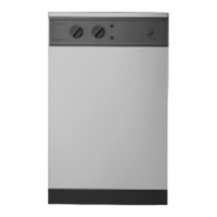
REAR VIEW
5
1
3
4
2
1. Alternative central heating return tapping.
2. Central heating flow (22mm compression).
3. Mains cold water in (15mm compression).
4. Pressure relief discharge pipe.
5. Domestic hot water out (22mm copper).
Boiler
152mm
168mm
112mm
Fig. 1. Pipework Dimensions.
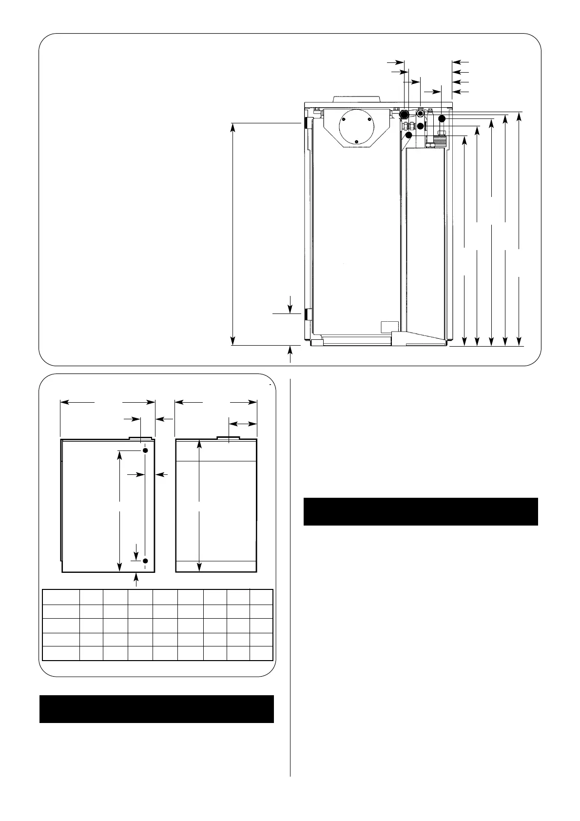
795mm
809mm
813 mm
769mm
738mm
37mm
FRONT VIEWSIDE VIEW
CD
E
AB
H
F
G
Fig. 2. Principal Dimensions.
110mm
(12/14,15/19, 20/25 ) 780mm
775mm (26/32)
MODEL A B C D E F G H
12/14
520 600 855 780 110 92 57 184
15/19 520 600 855 780 110 92 57 184
20/25 520 600 855 780 110 92 57 184
26/32 670 600 855 775 110 92 52 260
 Loading...


