27
15.1 After unpacking the appliance it is recommended that all
cabinet panels are removed, as described in Section 5, and
stored in a safe place to avoid damage during installation and
allow easy inspection for leaks after the system has been filled.
15.2 Remove the burner as described below and store in a safe
place until the appliance is ready for commissioning.
(a) Conventional Flue Appliance (CF/LLD).
1.
Remove the electrical lead plug by depressing the two locking
ears and pulling the plug downwards.
2. Remove the burner from the boiler by slackening the two M6
retaining screws located in the burner housing ring and pulling
the burner clear. This will require the use of a 5mm allen key.
(b) Room Sealed Balance Flue Appliance (RS).
1.
Remove the burner box cover by pulling forwards to release
the ball studs. This will be found easier by pulling on the one
side of the handle first to release two of the ball studs and then
repeating on the other side. Take care not to pivot the remaining
two ball studs too far around as this will cause damage to the
spring clips.
2. Remove the electrical lead plug by depressing the two locking
ears and pulling the plug downwards.
3. Push the electrical lead grommet back through the burner
surround box and feed the lead through the hole.
4. Remove the burner from the boiler by slackening the two M6
retaining screws located in the burner housing ring and pulling
the burner clear. This will require the use of a 5mm allen key.
15.3 Flue System Installation
Install the appliance flue system as described in Section 7.
15.4 Heating System Installation.
Before the appliance is fitted to the heating system
flush the system and mains water supply.
1.
Plumb the boiler into the central heating system.
2. Check that all unused sockets have been plugged.
3. The following procedure should be used when filling the
system:
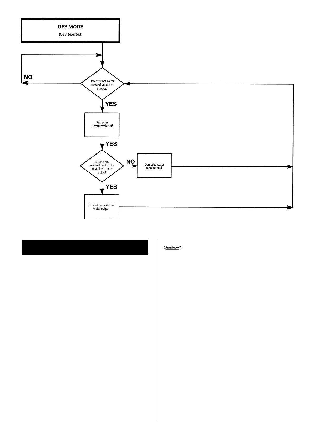
Set the diverter valve to the mid position by moving the lever on
the left hand side down to the middle position and locking in
position. Open all radiators and lockshield valves and remove
and discard the automatic air vent cap on the Heatslave tank .
Fill the system and check that air is being discharged from the
automatic air vent.
Vent each radiator in turn to remove the air from the system.
Bleed any air from the appliance pipework using the manual air
vents provided.
When the system has been completely vented, turn the
Domestic Hot Water Control Thermostat fully anti-clockwise and
set the user operating switch to heating and hot water on. The
pump will now operate and any remaining air can be purged
from the system using the appropriate bleed points.
Return the diverter valve lever to the normal right hand side
position.
4. Check the boiler and all pipework connections for leaks.
15.5 Domestic Water Installation
1.
Connect the incoming domestic water supply to the 15 mm
compression isolating valve.
2. Connect the main domestic hot water supply pipe to the hot
water outlet via a 22mm pipe, to ensure minimum pressure
drop in the circuit.
3. Ensure that no air traps are formed in the pipe-work as this
will cause the flow switch to bounce when a hot or cold tap is
15. Installation
 Loading...


