(See Figs. 12, 13 and 14).
8.1 Plastic or steel tanks should be installed to BS5410.
A steel tank should also conform to BS799: part 5 and be arranged
with a slope of 1 in 24 away from the outlet valve with a sludge
cock at its lower end.
8.2 Do not use galvanised steel tanks or pipework for the oil
supply system.
8.3 Do not use soldered joints in the oil supply pipework as this
could cause a hazard in the case of a fire.
8.4 The burners on all appliances are supplied so as to be
connected to a single pipe gravity feed system. Details of how to
convert the burners to a double pipe sub-gravity feed system
are shown in Fig. 12
8.5 Oil Supply System
(a)
Single Pipe System
If a single pipe system is employed, then the tank must be
positioned such that the oil level does not exceed 4 metres
above the level of the burner oil pump and in addition the oil
level must be at least 0.3 metres above the level of the oil pump.
Should it prove impossible to site the tank below the 4 metres
maximum oil level head breaking device must be installed
between the tank and the burner.
(b) Double Pipe System
If a double pipe system is used then the maximum suction
height allowable is 3.5 metres.
(c) Single Pipe Suction Lift with De-aerator
If a single pipe suction lift with a de-aerator is used, the oil tank must
be positioned below the burner. An inlet and return loop should be
created between the de-aerator and oil pump. The oil pump should be
connected as for a double pipe system. Details of how to convert to a
double pipe system are shown in Fig. 9.
Oil inlet and return flexible hoses should be connected to the oil
pump inlet and return ports.
Table 12 is a general guide to determine the maximum allow-
able pipe run when using a de-aerator.
Table 12 does not override the de-aerators manufacturers
instructions and should only be used in conjunction with the
manufacturers instructions.
If a non-return valve is not incorporated within the de-aerator
unit, a non-return valve should be fitted in the oil line between
the oil tank and the de-aerator.
NOTE: If a de-aerator is used it should be fitted externally to the building.
8.6 Oil Supply Pipework
a)
The oil supply pipe diameter can be determined using Tables 10,
11 and 12 depending on whether a single or double pipe system or
single pipe suction lift system is being installed. Selection of the
correct pipe diameter will depend on the position of the oil storage
tank relative to the burner and the length of pipe run.
b) The oil supply pipe should be laid as level as possible to avoid
air pockets and unnecessary friction losses.
c) The following components should be fitted in the fuel line
between the storage tank and burner:
1. A Manual isolating valve installed as close to the tank as possible.
2. A fire valve in accordance with BS5410, Part 1 as shown in Fig
11. The fire valve should be fitted externally with a fire detection
element located within the appliance case. Use of a capillary type
valve will allow a neat and simple installation. A suitable valve is the
KBB manufactured by Teddington Controls Limited. A spring clip
has been provided behind the electrical panel on CF/LLD models,
shown in Fig 3 and 5, and on the burner box on RS models, shown
in Fig 4 and 6, to allow a fire valve element to be mounted.
Alternatively a fusible link or electrical system may be used. Under
no circumstances should a combination isolating/fire valve be used
as the sole fire protection device.
3. An oil filter should be fitted close to the oil storage tank. If
there is doubt about the internal oil line condition, a further filter
should be fitted near the boiler.
8. Oil Supply
15
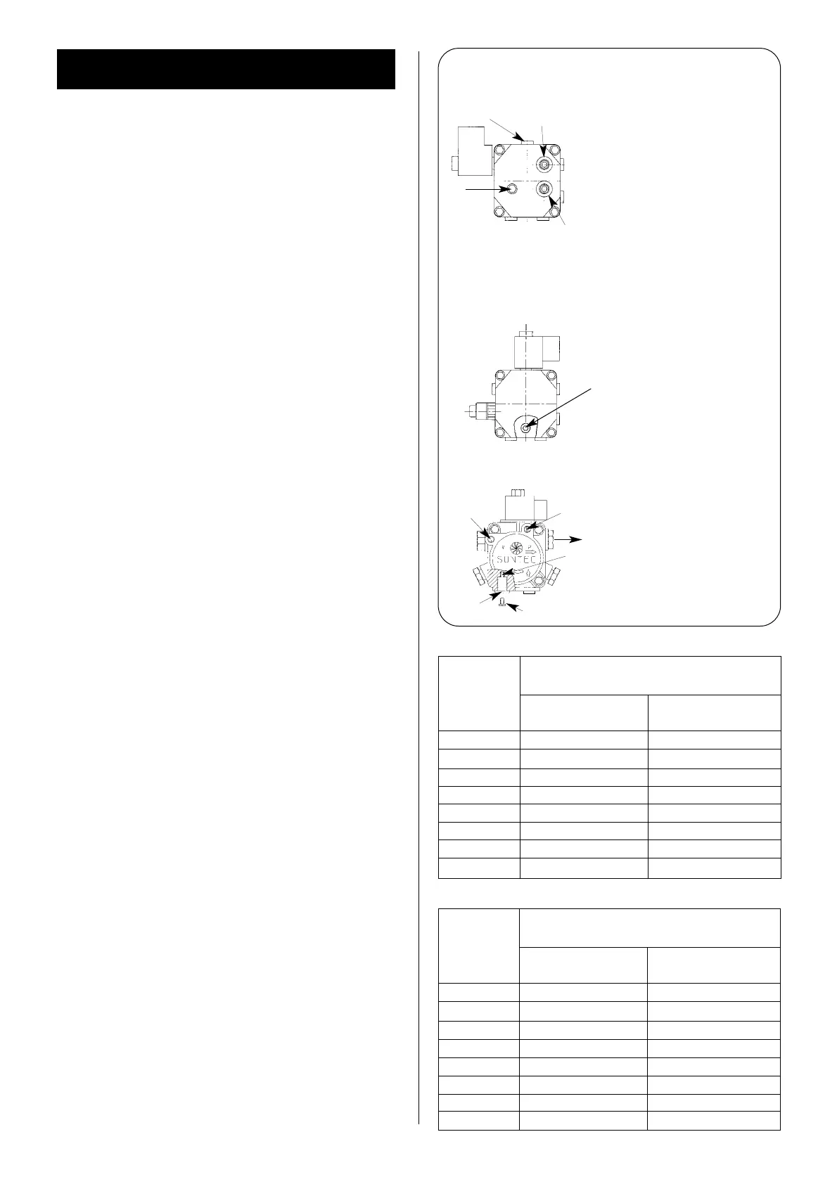
Fig. 12. Oil Pump.
B. Danfoss BFP 11 Oil Pump.
A. Danfoss BFP 41.
C. Suntec AS47C Oil Pump.
Cartridge filter
12
3
4
4a
5
6
1
2
3
4
5
6
A
1 INLET
2 RETURN
3 BLEED AND PRESSURE
GAUGE PORT
4 VACUUM GAUGE PORT
5 PRESSURE ADJUSTMENT
6 NOZZLE OUTLET
To convert to a double pipe sys-
tem, remove plug 4a and insert
the grub screw provided into the
threaded hole. Connect flow and
return pipes to (1) and (2).
To convert to a double pipe sys-
tem: Remove the pump front
cover, remove the changeover
screw (A) nearest to ports 1 and
2, and the horseshoe washer
underneath. Replace the
changeover screw back into the
threaded hole. Connect the flow
and return pipes to 1 and 2.
Note: When removing the pump
front cover ensure that a suitable
receptacle is placed below the
pump to catch the oil residue.
To convert to a double pipe sys-
tem, remove the return port plug
(2) and insert the grub screw (A)
provided into the threaded hole
(B). Connect flow and return pipes
to (1) and (2).
1
2
3
3
4
5
B
A
TABLE 10 Single Pipe Gravity Feed System
MAXIMUM ALLOWABLE PIPE RUN
HEAD (metres)
(metres)
8 mm inside dia. pipe 10 mm inside dia. pipe
(10 mm O.D. copper) (12 mm O.D. copper)
0.5 12 30
1.0 25 69
1.5 37 91
2.0 49 100
2.5 62 100
3.0 74 100
3.4 87 100
4.0 99 100
TABLE 11 Double Pipe Sub-Gravity Feed System
MAXIMUM ALLOWABLE PIPE RUN
HEAD (metres)
(metres)
8 mm inside dia. pipe 10 mm inside dia. pipe
(10 mm O.D. copper) (12 mm O.D. copper)
0 50 100
0.5 44 100
1.0 38 95
1.5 32 80
2.0 26 66
2.5 20 51
3.0 14 37
3.5 8 22
 Loading...


