16
MAXIMUM ALLOWABLE PIPE RUN FROM TANK TO DE-AERATOR (metres)
Fuel
Flowrate 2.5 (kg/h) 5.0 (kg/h) 10.0 (kg/h) 10.0 (kg/h)
HEAD
(metres)
6 mm inside dia. pipe 8 mm inside dia. pipe
(8 mm O.D. copper) (10 mm O.D. copper)
0 100 55 26 100
0.5 95 45 23 100
1.0 80 40 20 90
1.5 70 35 17 75
2.0 60 30 14 65
2.5 45 25 11 50
3.0 35 15 8 35
3.5 25 10 5 20
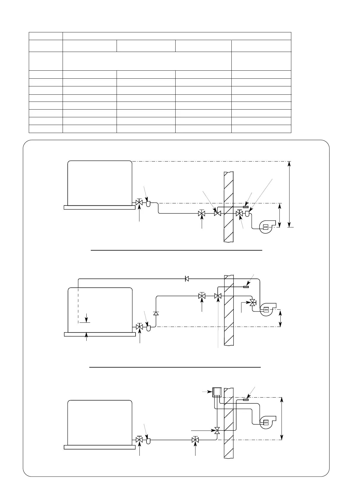
Fig. 13. Oil Supply.
(a) Single pipe system
Oil tank
Oil tank
Maximum oil level
H = 4 m (13 ft) maximum
Fire valve to
BS 5410 Part 1
Fire valve to
BS 5410 Part 1
Isolating
valve
Isolating
valve
Fire detection
element
Filter
Burner
Burner
Wall
Wall
(b) Double pipe system.
Isolating
valve
Non return
valve
Non return
valve
Fire detection
element
Isolating
valve
Oil tank
(c) Single pipe lift system with de-aerator.
Fire valve to
BS 5410 Part 1
H = 3.5 m (11.5 ft) maximum
Burner
Wall
Fire detection
element
De-aerator
H = 3.5 m (11.5 ft) maximum
TABLE 12 Single Pipe Suction Lift with De-aerator
Isolating
valve
H = 0.3 m (1 ft) minimum
Paper element
oil filter
Isolating
valve
Filter
Filter
Isolating
valve
Isolating
valve
Full base
(for plastic tanks)
Full base
(for plastic tanks)
Full base
(for plastic tanks)
150 mm
 Loading...


