The flue pipe fits into the spigot and should be correctly sealed
with fire cement.
NOTE: The flue size must never be reduced from the take-off
diameter. An increase in flue size is permissible provided that
the joint is sealed correctly.
The flue should be vertical and contain as few bends as possible.
Where bends are necessary, a maximum of two are permitted
and 135° bends should be used.
All brick and masonry chimneys should be lined with a suitable
non-combustible material. They must be properly jointed and
able to withstand the effects of the working temperature of the
appliance and any condensate which may form.
Down-draught conditions will adversely affect the operation of
the appliance and must be avoided. Where possible, the flue
should be extended beyond the apex of the roof and should
always be taken beyond the eaves of the building. Where down-
draught is experienced a suitable anti-down-draught terminal
should be fitted to the flue termination.
The natural flue draught must be checked. A suitable location for
checking this is located in the flue outlet plate on top of the boiler.
The draught should be no less than 0.75mm w.g and no greater
than 5.1mm w.g. If a flue draught greater than 5.1 mm w.g is
experienced a draught stabiliser should be fitted to the flue and
adjusted to achieve a flue draught within the specified range.
7.2 Low Level Discharge (LLD)
See Fig 8.
The conventional flue appliance may be converted to discharge
the products of combustion at low level. For this purpose a
special flueless kit and associated ducting is available, allowing
the conventional flue to be discarded. Detailed instructions for
converting the appliance to low level discharge are supplied
with the conversion kit. The flue spigot should be removed from
the flue outlet plate by undoing the three retaining screws and
the hole blanked off with the plate provided in the kit.
NOTE: Under no circumstances may 35 Second Gas Oil be
burned with this type of flue terminal arrangement.
7.3 Room Sealed Balance Flue Model (RS)
The appliance is supplied ready for installation as a low level
discharge balanced flue system by the simple addition of one of
the flue terminal options shown in Fig.9.
Details of the installation procedure are included in the Flue
Terminal Installation Instructions supplied with the terminal kit.
Alternatively, a range of room sealed balanced flue kits are
available to convert the appliance to discharge the flue products
to the left, right, at a higher level, or vertically up to a roof height
of 4.5 metres.
13
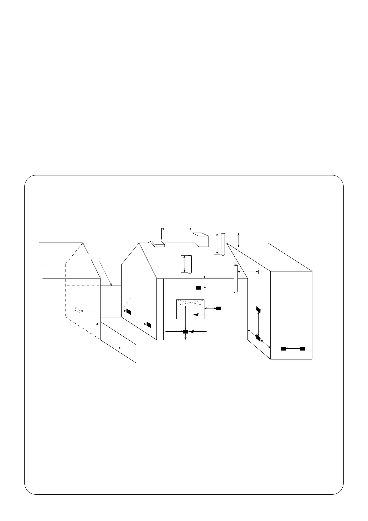
Minimum Distance (mm)
Terminal Position Open Low-Level Vertical
Flue Discharge Balanced Flue
A Directly below an opening, air brick, window, etc. .......................................... Not allowed 600 Not allowed
B Horizontally to an opening, air brick, window, etc. ........................................ Not allowed 600 ''
C Below a gutter or sanitary pipe if combustible material protected. .............. Not allowed 75 ''
D Below a balcony, eaves, gutter or drainage without protection
to combustible material. ...................................................................................... Not allowed 600 ''
E From vertical sanitary pipework.. ....................................................................... Not allowed 300 ''
F From an internal or external corner or boundry along side terminal. .......... Not allowed 300 ''
G Above ground or balcony level. .......................................................................... Not allowed 300 ''
H From a surface or boundry facing the terminal. .............................................. Not allowed 600 ''
J From a terminal facing the terminal. ................................................................. Not allowed 1200 ''
K Vertically from a terminal on the same wall. ................................................... Not allowed 1500
L Horizontally from a terminal on the same wall. .............................................. Not allowed 750 ''
M Above an intersection with the roof. ................................................................. 600 Not applicable 732
N From a vertical structure on the side of the terminal...................................... 750 Not applicable 750
O Above a vertical structure less than 750mm from the side of the terminal. 600 Not applicable 732
P From a ridge terminal to a vertical structure on the roof................................ 1500 Not applicable Not applicable
NOTE: The dimensions given are for general guidance only. Other surrounding buildings or objects may affect the clearance of
combustion products. An alternative flue terminal position should be sought when there is any possibility of a nuisance being
caused by inadequate dispersal of flue products.
Terminals should be positioned so as to avoid products of combustion entering into buildings.
Fig. 10. Flue terminating positions for oil-fired appliances
Window
Flue
Terminal
 Loading...


