The mains supply cable should be connected into the mains
connection points on the control board marked L (Live), N
(Neutral) and E (Earth) on the control board and securely held in
the cable clamp located on the base of the electrical box. To
secure the cable, remove the clamp retaining screw and pull its
inner body out to allow the cable to be fed through. With the
cable in position refit the screw and fully tighten to grip the
cable. Feed the cable between the side panel and the boiler
insulation jacket and route to the connection point avoiding any
hot surfaces.
The appliance must be earthed.
13.4 Facia Mounted Programmer
(See Fig. 21a)
A plug in, colour co-ordinated, 2 channel electronic programmer
is available from Worcester Heat Systems. The programmer will
give fully independent central heating (CH) and hot water (HW)
programmes when the switch on the rear of the unit is set to P.
Full instructions covering installation and operation of the
programmer are included with the kit.
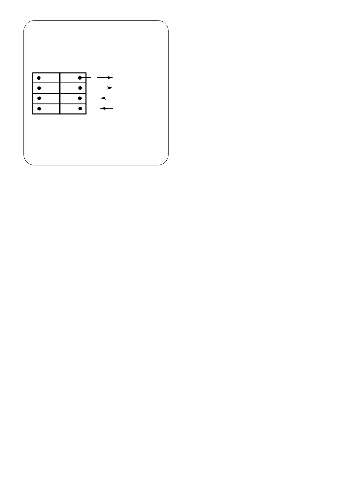
13.5 External Programmer
(See Fig. 21b)
A programmer offering time controlled central heating and
domestic hot water or one which provides controlled central
heating and switched domestic hot water is acceptable.
Fitting an external programmer:
Check that the electrical supply has been turned off and remove
the facia panel as described in Section 19.2 (15).
The external programmer must take its power supply from the
appliance. See Fig. 21b. The leads must be insulated as they
operate at mains voltage.
Pass the leads through the hole provided in the control box
back panel and connect them to terminal block
X4 to which
the leads from the facia mounted switch are currently still
connected. See Fig. 21b.
Disconnect the grey lead from the terminal block and connect,
in its place, the central heating control lead from the
programmer.
Disconnect the white lead from the terminal block and connect,
in its place, the domestic hot water control lead from the
programmer.
Disconnect the brown lead from the terminal block and connect,
in its place, a brown lead (live supply) to the programmer.
The remaining connection in the block is the neutral connection
for the programmer.
Where an earth point is provided on the programmer then this
should be wired to the appliance control box earth point on the
X1 terminal block.
Although inoperative, the facia mounted switch should be left in
place. Remove the spade connectors from the user operating
switch and discard the wires removed.
Refit the facia and set the programmer.
Check the operation of the appliance in response to the
switching of the programmer.
NOTE: Under no circumstances should the timer be connected
to a separate electrical supply. Safety is assured fom a sigle
fused supply to the boiler.
13.6 External Thermostats
If a room and/or frost thermostat is to be fitted, refer to Fig 20.
The thermostats must be suitable for use on mains voltage.
An optional earth point is provided on the
X1 terminal block if
required.
Frost protection will be lost if there is no power supply to the
appliance.
13.7 Safety Check
In the event of an electrical fault after the installation of the
appliance, the electrical system shall be checked for short
circuits, fuse failure or incorrect polarity of connections.
23
Fig. 21b. External Programmer
Connections.
Neutral to programmer
Live supply to programmer
Switched domestic hot
water from programmer
Switched central heating
from programmer
Terminal Block
X4
on Control Board
bl
br
w
g
 Loading...


