Withdraw the diverter valve and fit replacement in reverse order.
NOTE: A residue of water will remain in the diverter valve.
Open the valves and fill the system as described in Section 16.
4. Heatslave Tank
Check that the electricity and mains water supplies have been
turned off.
Remove the appliance front, top and left-hand side panel.
Withdraw the burner to prevent water ingress.
Drain the boiler and Heatslave tank.
Remove the electrical control box as described in Section 19.2 (11).
Remove the flow switch assembly and the domestic hot water
heat exchanger as described in Sections 19.2 (8) and 19.2 (9)
Undo the compression fitting connecting the diverter valve to
the Heatslave tank and remove the M6 nut and bolt holding the
Heatslave tank onto the appliance base.
Remove the pressure relief valve as described in Section 19.2 (6).
Move the tank slightly to the left to dislodge the diverter valve
fitting from the tank.
Raise the front end of the tank sufficiently to clear the base lip
and withdraw the tank.
Remove the remaining components from the tank and refit to
the replacement tank.
Fit a replacement tank in the reverse order.
Open all valves and fill the system as described in Section 16.
5. Expansion Vessel
Check that the electrical supply has been turned off.
Remove the appliance front panel and withdraw the burner to
prevent water ingress.
Drain the boiler
Undo the nut connecting the vessel flexible pipe to the boiler.
Withdraw the vessel by lifting upwards and pulling out and
replace in the reverse order.
Open all valves and fill the system as described in Section 16.
6. Pressure Relief Valve
Check that the electrical supply has been turned off.
Remove the appliance front panel, top panel and withdraw the burner.
Drain the boiler.
Undo the compression fitting connecting the pipe to the relief
valve.
Undo the union nut on the right hand side and withdraw the
relief valve, taking care not to lose the fibre washer seal.
Fit a replacement valve in the reverse order.
Open all valves and fill the system as described in Section 16.
7. System Pressure Gauge
Check that the electrical supply has been turned off.
Remove the appliance front panel and withdraw the burner.
Drain the boiler.
Turn off the isolating valves mounted on the outlet of the pump
and the boiler body, and drain the residual water via the drain
plug below the pump inlet.
Unscrew the gauge from the pump inlet manifold.
Fit a new gauge in the reverse order.
Open all valves and fill the system as described in Section 16.
8. Domestic Hot Water Heat Exchanger
Check that the electricity and mains water supplies have been
turned off.
Remove the appliance front panel, top panel and withdraw the
burner to prevent water ingress.
Drain the boiler and approximately 1 litre of water from the
Heatslave tank using the drain point provided at the bottom
front face of the tank. This will prevent excessive residual
spillage from the pipework when disconnecting.
Close the mains water isolating valve located on the flow switch
inlet pipe. Undo the compression fitting connecting the flow
switch to the isolating valve. Undo the union nut connecting the
flow switch to the heat exchanger and remove the flow switch
assembly.
Drain the residual water from the hot water pipework and undo
the union nut connecting the pipework to the heat exchanger.
Undo the two remaining union nuts located on the domestic hot
water heat exchanger.
Take care not to lose any of the four tap washers and replace
any which are damaged.
Withdraw the heat exchanger and fit a replacement in the
reverse order.
Open all valves and fill the system as described in Section 16.
NOTE: It may be advantageous to use a tap spanner when
undoing the heat exchanger union nuts.
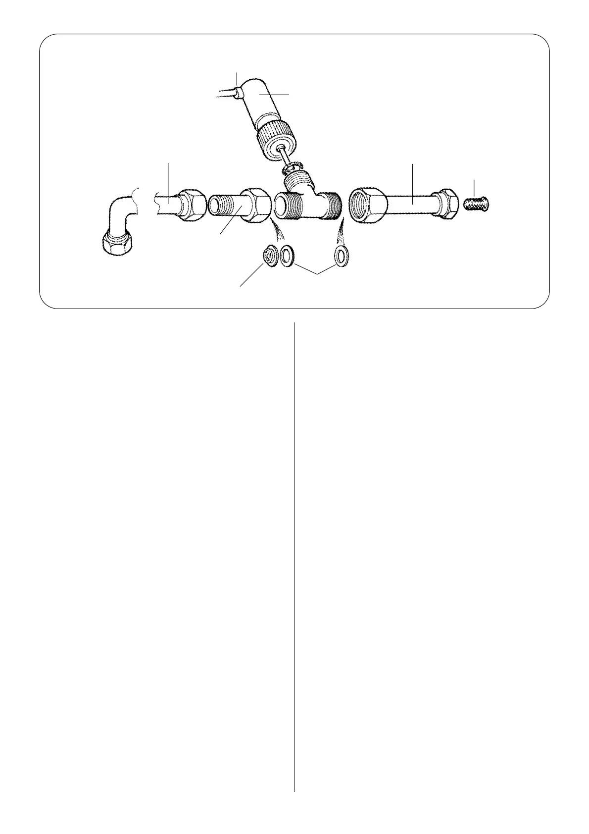
9. Flow Switch. (See Fig 28)
Check that the electricity supply and mains water supplies are
turned off.
To replace the Flow Switch proceed as follows:
NOTE: Do not replace individual components of the Flow Switch,
it must be replaced as a whole unit.
Remove the appliance front panel, top panel and withdraw the
burner to prevent water ingress.
Remove the control box top cover.
35
Proximity switch
Flow switch body
Pipe – Flow switch to
water-to-water heat
exchanger
Regulator compression
fittings
Flow restrictor body
Fibre washer
Filter
Pipe – Domestic inlet
assembly
Fig. 28. Flow Switch Assembly.
 Loading...


