9
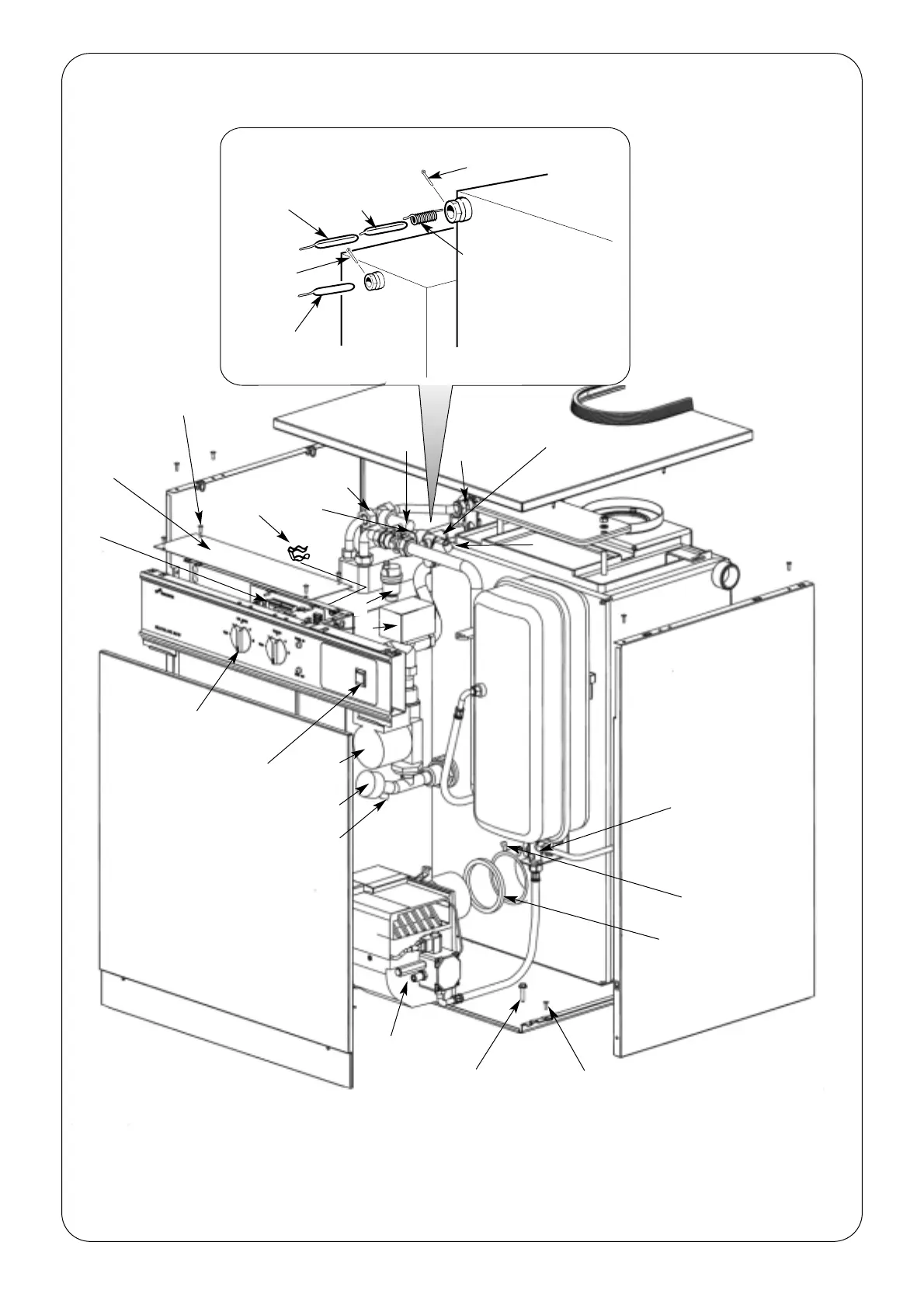
Fig.5. 26/32 Conventional Flue Appliance (CF/LLD).
Electrical Box Assembly
Front panel
Burner
Thermostat knob
Control board
Electrical box top
cover
User operating switch
(optional programmer
position)
Burner seal gasket
Isolating valve
Burner locking screws
Side panel
Top panel
Side panel locking
screw (A)
1. Hot water check valve. 7. Alternative central heating return tapping.
2. Automatic air vent. 8. Flow switch.
3. Diverter valve. 9. Mains cold inlet isolating valve.
4. Pump. 10. Pressure relief valve.
5. System pressure gauge. 11. Air vent.
6. Pump manifold drain. 12. Fire valve clip.
6
5
4
3
10
9
1
8
7
2
Expansion
vessel
1010
1
11
Base plate locking
screw
12
Access cover locking
screw
Split pin
Split pin
Boiler high
limit
thermostat
phial
Central heating
control
thermostat
phial
Domestic hot
water control
thermostat phial
Manual reset high
limit thermostat
phial
 Loading...


