Marine Installation
975-0784-01-01 41
Marine Installation
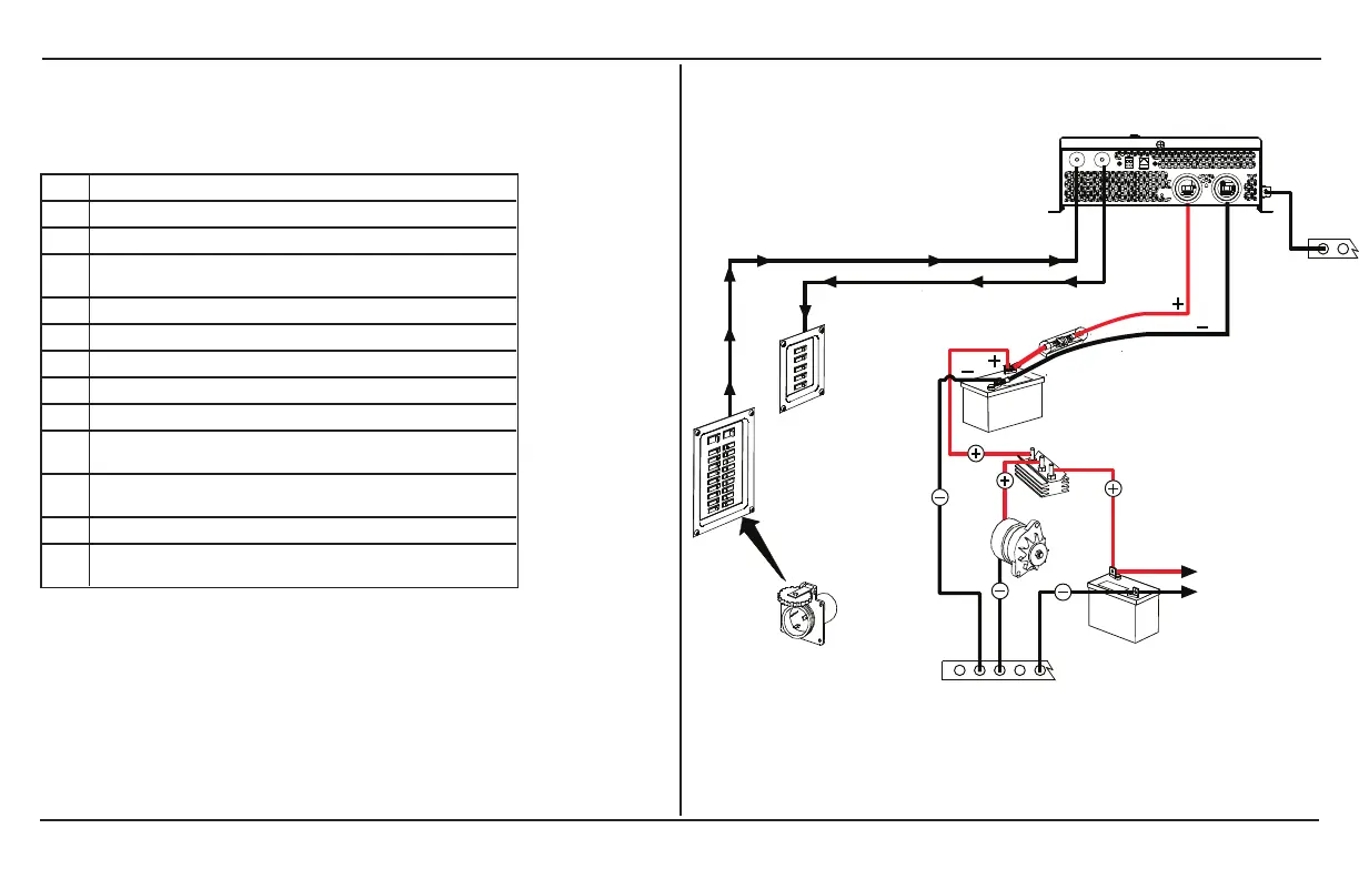
Figure 13 illustrates a typical marine installation with the following
components:
1 Equipment ground – Engine negative bus / DC ground bus
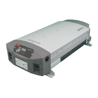
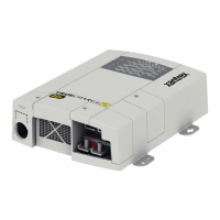
2 Freedom XC
3 DC fuse/disconnect/DC circuit breaker
4
12V deep cycle battery bank (house) and protected by a DC fuse in the
positive cable
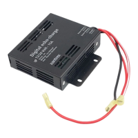
5 Battery isolator
6 DC alternator
7 To engine
8 Equipment ground – Engine negative bus / DC ground bus
9 Starting battery
10
AC load panel with branch circuit breakers that supply only loads that run
off the Freedom XC
11
AC source panel that includes a max 30A (or a 15A if using a GFCI) circuit
breaker that supplies the Freedom XC
12 Shore power – AC power supplied from a shore power connector
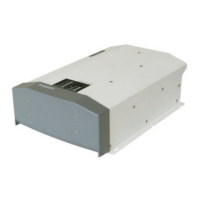
Not
shown
Drip shield (see next page)
Figure 13 Typical Marine Installation
 Loading...