42
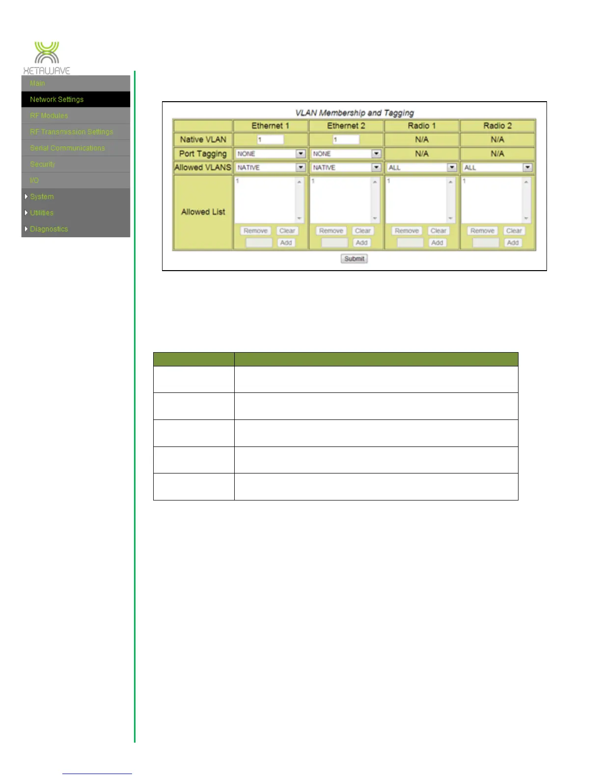
3.2.1 VLAN Configuration
XetaWave Ethernet radios function as 5-port Enterprise Ethernet switches by
implementing 802.1q VLANs and trunks. The five ports that participate in the Ethernet
switching process are:
Physical Ethernet interface which can function as an access
port, an 802.1q trunk, or both.
Physical Ethernet interface which can function as an access
port, an 802.1q trunk, or both.
Wireless interface which functions as an 802.1q trunk.
Wireless interface which functions as an 802.1q trunk.
Virtual Ethernet interface internal to the radio which
functions as an access-port.
Native VLAN – this is the primary VLAN ID associated with a physical Ethernet
port. By convention, untagged Ethernet frames entering the radio via a physical
Ethernet port are assigned to the native VLAN specified for that port. Any
untagged frames leaving an Ethernet port are also associated with the port’s
native VLAN. The default setting is 1.
Port Tagging – this value controls the VLAN tagging behaviour for an Ethernet
port. The default setting is NONE.
When set to “NONE” an Ethernet port does not add VLAN tags to any
frame leaving the port and only untagged frames are allowed to enter the
radio. (One exception to this rule: tagged frames belonging to the native
 Loading...