52
3.5 Serial Communications
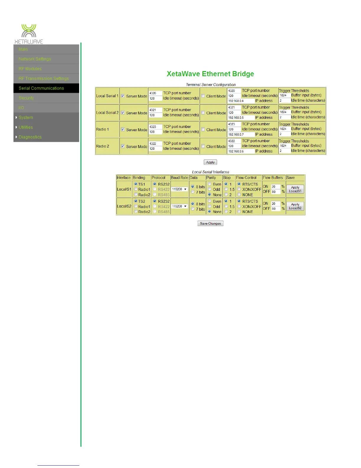
There are two sets of terminal servers that need to be set; one pair for the user
accessible ports on the enclosure and a second server(s) for the radio (either one
terminal server for one radio or two terminal servers for the two radio configuration).
The “Local Serial 1” and ”Local Serial 2” correspond to the COM Port 1 and COM Port 2
connections at the front of the radio while the “Radio 1” and “Radio 2” correspond to
the one or two internal RF modules. The terminal servers may be set in “Server Mode”
whereby they listen on the TCP port that is set. If the terminal server observes traffic on
that port, then it creates a session to manage the data. The session will end if
commanded or if the “Idle Timeout” time is reached with no traffic on the port. The
terminal server may also operate in “Client Mode” where the port initiates a session to
the specified “IP address” and “TCP port number”. Thus, data present on the serial port
will be sent to the destination IP address. Again, there is an “Idle timeout” specified so
that if the destination stops responding, the session will be terminated.
“Trigger Thresholds” should normally be left at 1024 bytes and 2 character idle time.
The thresholds determine when to send data to the radio for the RF link. If the “Buffer
Input” is filled by the serial data, then the data is sent to the radio, however, if an idle
time is detected before the buffer is full, then only that portion of the buffer is sent to
the radio for immediate transmission.
 Loading...