5
The limits for Industry Canada are in Watts per square meter and easily calculated from
equations 2 and then 1 above.
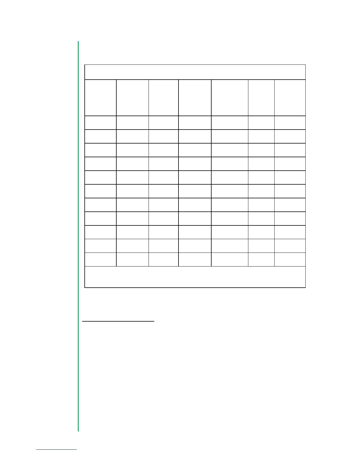
Table of MPE Safe Distance vs. Antenna Gain and Power Output Setting
*The worst case is 4000 mW and an antenna with 6 dBi gain or greater or 33.96 cm
as power output is reduced as required by the appropriate regulating authority.
Antenna installation
US/FCC antenna compliance
Since professional installation is required, standard RF connectors are used. Adapters or
custom coaxial cables may be required to connect the radio output connector to the
desired antenna.
Any antenna from a reputable manufacturer with desired bandwidth, gain/pattern
coverage, and have an input surge impedance of approximately 50 ohms can be used
provided the requirements of Title 47 CFR Part 51.247 (a), (b) and (c) are met, i.e.
conducted power of 1W (30 dBm) or EIRP of 4W (36 dBm) maximum and if the antenna
 Loading...