74 www.xilinx.com ML605 Hardware User Guide
UG534 (v1.9) February 26, 2019
Chapter 1: ML605 Evaluation Board
ML605 Board Power Monitor
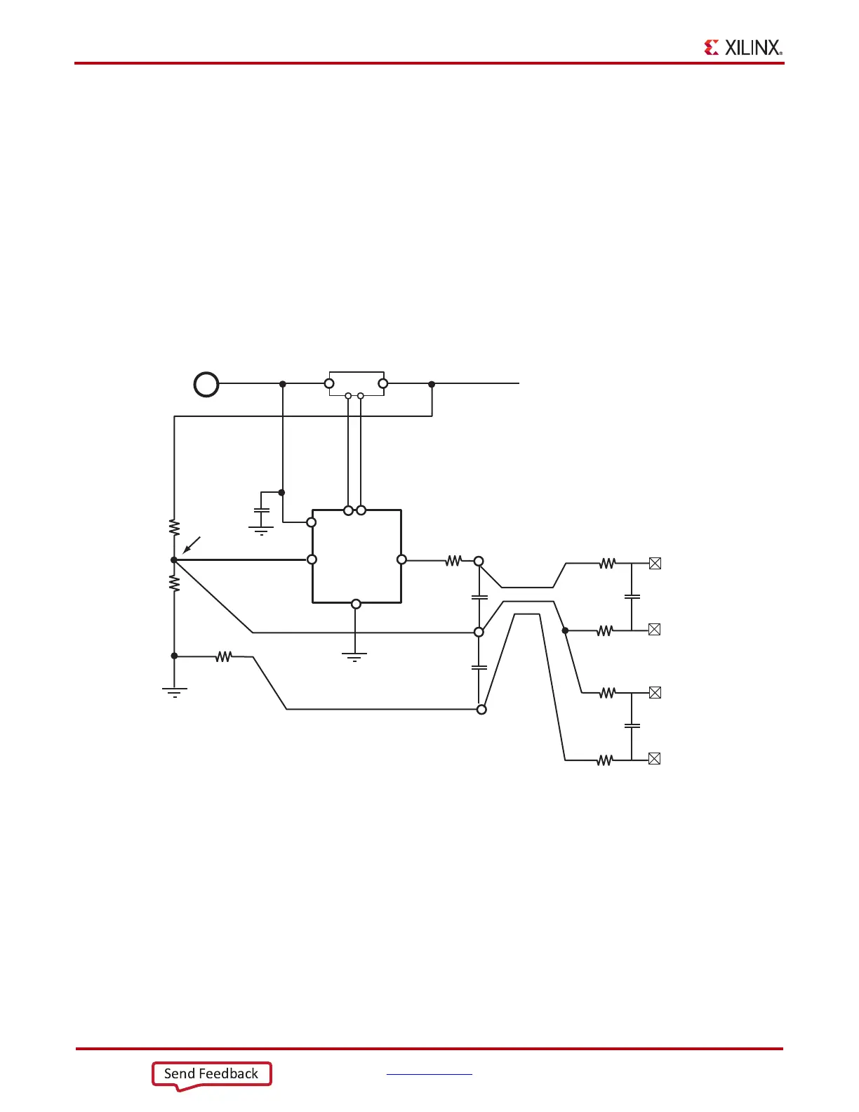
In addition to monitoring the FPGA core supply power consumption, two auxiliary analog
input channels (of the 16 that are available) are used to implement a power monitor for the
entire ML605 board. The board power is monitored at the 12V power input connector.
Figure 1-31 shows how the power monitor is implemented and connected to the System
Monitor auxiliary input channels 12 and 13. A simple resistor divider is used to monitor
the 12V supply voltage and to provide a reference voltage to an instrumentation amplifier
(InAmp). The voltage on the auxiliary channel 12 is equal to supply voltage divided by 24
(~ 0.5V).
The InAmp is used to amplify (by a factor of 50) the voltage dropped across a 2 mΩ current
sense shunt. The voltage at the output of the InAmp is proportional to the current. The
voltage on auxiliary channel 13 = Current (amps) x 0.002 x 50 (e.g., 5A = 0.5V).
X-Ref Target - Figure 1-31
Figure 1-31: ML605 12V Power Monitor
12V Supply Monitor
11.5k ±0.5%
499 ±0.5%
~470
~470
10nF
1k
1k
V
AUXP[13]
Current Channel
Voltage Channel
V
AUXN[13]
INA213
GND
OUT
REF
R1
R2
IN+
IN-
V+
2m ±1%
SC70-6
Package
50V/V
~0.5V
10nF
1k
1k
V
AUXP[12]
V
AUXN[12]
K1
K2
100nF
10nF
10nF
UG534_38 _081209