Qdesys Sensorless Field Oriented Control Quick Start Guide
© Copyright 2012 Xilinx
31
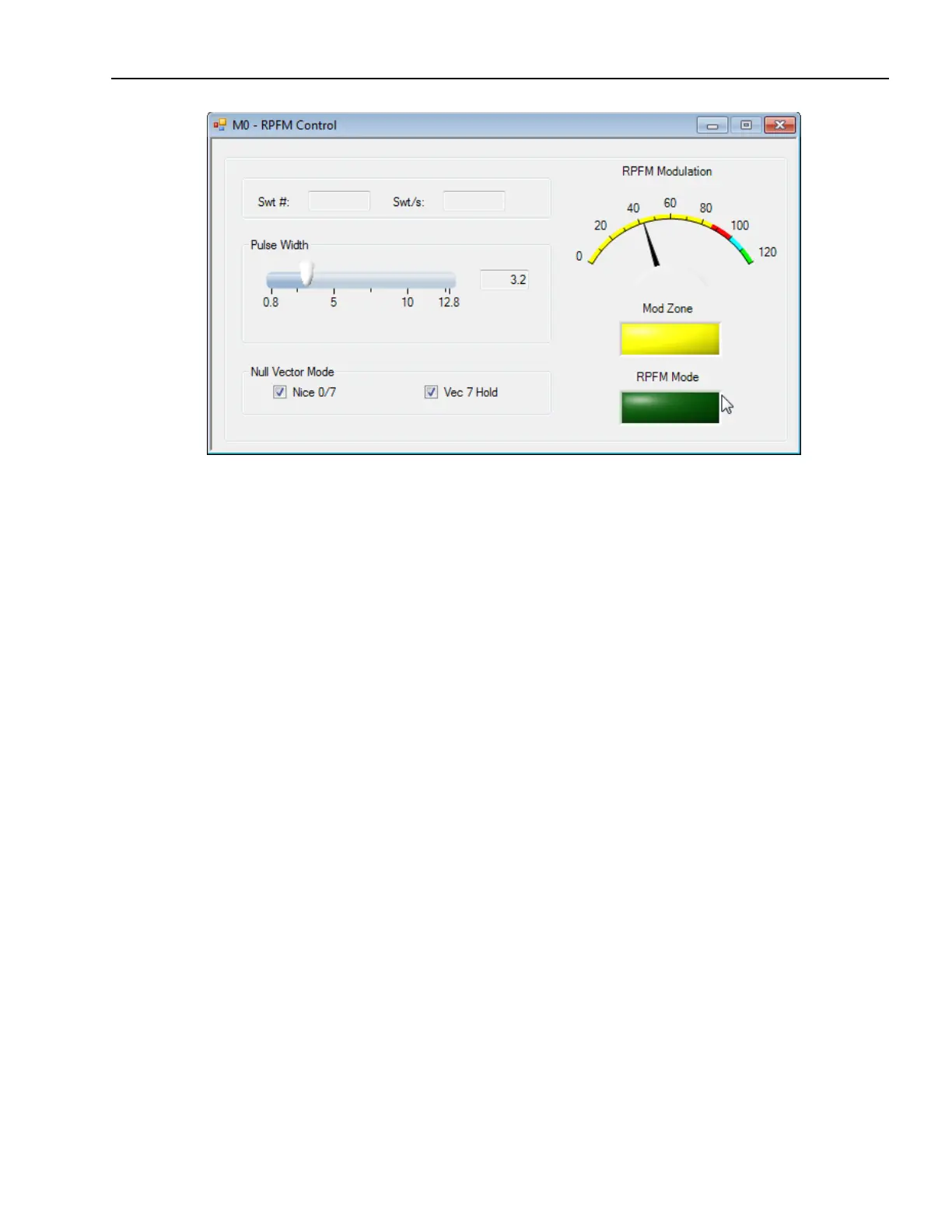
RPFM Panel Description
The RPFM Mode led reports the active status of RPFM modulator. The light green value
indicates that it is operating; the dark green (OFF) indicates RPFM is not operating. Clicking on
RPFM led will activate the RPFM itself.
NOTE: The current implementation drives the three phase’s motors only; for stepper motors
RPFM is not implemented.
The Mod Zone LED reports the saturation zone of RPFM modulator. The colors are:
Yellow: Sinusoidal wave (sine waveform + space vector waveform)
Cyan : Hexagon saturation zone,
Green: Square wave; also called six steps for 3-phase motors
These values are reported by the RPFM IP in real time.
The Meter reports the modulation level of RPFM modulator. The colored zones refer to:
Yellow : sinusoidal modulation; from 0% to 86.603%,
Red : space vector; from 86.603% to 100%,
Cyan: hexagon saturation zone; from 100% to 110.266%,
Green: square wave zone (six steps); from 110.266% and over.
The RPFM Pulse Width can be changed according the specific motor electric characteristics.

 Loading...
